This thread has been locked.

If you have a related question, please click the "Ask a related question" button in the top right corner. The newly created question will be automatically linked to this question.

UC3843: How to sense the current ramp of UC3843

Part Number: UC3843
Other Parts Discussed in Thread: LM358

Hi Team,

Our customer would like to know how to sense the current ramp of UC3843. Here are the details of his inquiry.

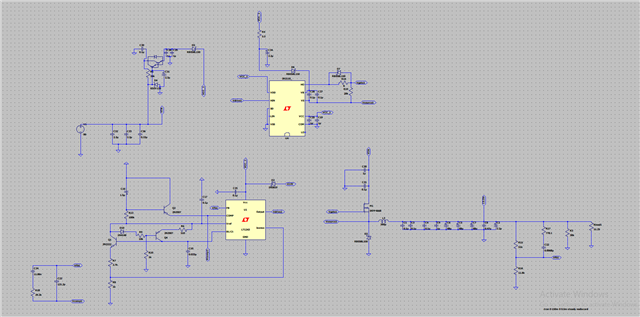
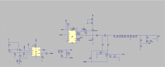
I am using UC3843 to design a buck converter in current mode control. How can I sense the current ramp effectively? I am using a small resistor value in series with the inductor then amplifying it with an opamp.(lm358)

I am getting a discontinuous conduction mode in the inductor yet I designed it for continuous conduction mode. I am using ltspice for simulation

This DCM mode is affecting the voltage ripple I am getting at the load. How can I sense this current for voltage ramp generation?

It is to step down (50V - 95V) input to 5V 3A output

I found the Simplifying Current Sensing application notes in the link below. Can he use the circuit of Figure 2 at page 34 for his application?

www.ti.com/.../slyy154a.pdf

Regards,

Danilo

  • Danilo,

    50V to 5V is 10% duty...not too bad but 95V to 5V is ~5% duty cycle which could be difficult depending on your switching frequency. For 5 A and R=15 mΩ, this only gives an average signal of ~75 mV. Depending on the frequency you are switching and what is your actual on-time, I'm not sure the LM358 is up to the task here. And if it works in simulation, can you actually build the circuit when PCB parasitics and real device parameters are introduced? If you're only in simulation, how far off is the DCM/CCM boundary based on your calculated inductor and time base? A quick way to verify your power stage calculations is by using TI Power Stage Designer which you can download here.

    Also for peak current mode control the UC3843 only needs the peak current information to control t_on. Your current sense resistor is sensing T=t_on+t_off and will dissipate more power in this location than if you sense in series with the high side switch. Some MOSFETs are designed with a kelvin sense across the drain-source channel for the purpose of RDS(ON) current sensing. For simulation, try a CS resistor in series with the MOSFET source?

    Regards,

    Steve M

  • Hi Steve,

    Here is the response of our customer.

    Thanks for your reply. You have mentioned that 5% duty cycle is hard to achieve with uc3843. Why is this yet the datasheet says that it can handle from 0-100% duty cycle? What is the recommended minimum duty cycle? I have a switching frequency of 100Khz

    Regards,

    Danilo

  • Danilo,

    The controller is capable of operating from 0% to 100% duty cycle but in a real switching converter application, achieving such small duty cycle is not easy when you consider PCB layout, parasitics, rise and fall time of MOSFET gate, etc. Different combinations of RT*CT can be used to achieve 100 kHz. For the purpose of achieving min duty it helps to select your RT, CT values, using a large CT and small RT...For 100 kHz, try something like RT=4 kΩ, CT=4.7 nF.

    Steve M

  • Hi Steve,

    Please see the response of our customer below.

    Does this concept apply to all smps controllers or is it specific to uc3843?
    Alternatively, I have two buck converters, One is outputting 13.5V and the other 5v. I am using the 13.5V one to provide Vcc to the controllers after power up. Can I instead step down the 13.5V to 5v instead of stepping both of them down from 95V? Where the 5v buck converter will be the downstream converter with respect to the 13.5v buck converter which will be the one connected to the 95v source?

    Regards,

    Danilo

  • Danilo,

    Applies to most PWM controllers, try controlling the duty cycle down to 1%...not easy and when it is shown it's usually demonstrated with a high speed digital control. The UC3843 is robust and reliable but it's also produced on bipolar process as opposed to high-speed BiCMOS.

    95V to 13.5V to 5V all in series is not good for your efficiency since the total will be the product of each individual converter. Your input voltage is only varying by 2:1 and if you want 13.5V for VCC how about chopping the DC through a transformer with ratio VINmin:VCC (50:14=3.6). You could use an open loop push pull for this, the output uses an LC filter on the push-pull secondary but there's no feedback, no compensation to deal with. The output of the push-pull now provides 14V<VIN<28V to the buck and it's a current fed buck so you have less capacitance on the buck input. the buck also has an LC output so now you have continuous input and output current.

    Regards,

    Steve

  • Hi Steve,

    Thank you for your comments, Our customer has follow up inquiry below.

    Another question I have based on my simulation is that I have a high inrush current at start up yet I have soft start implemented. What I am doing at startup is using a linear regulator which I implemented using a Darlington pair to provide vcc to the ic for a short time then tapping the output of the 13.5v buck converter to provide vcc. My reason for doing this is to limit the power dissipation by the linear regulator since it will only be on for a very short time. I am not sure if this is what is causing the soft start not to work. Let me send you a snap shot of the circuit I am simulating.

    Regards,

    Danilo

  • Danilo,

    I hope that I've help contribute to the original post about current sensing? Keeping the conversation close to the subject thread helps improve the search accuracy for the entire E2E community. Since this topic has shifted from the original post title, I'm going to close it and ask that if additional IC support is needed, you can open a new thread with a thread title related to your inquiry? Thanks for connecting through E2E.

    Regards,

    Steve

  • Hi Steve, 

    Thank you very much for your help. I created another post for the customer's additional inquiry. Related to this post, our customer would to clarify what do you mean by its a current fed buck and does not need much input capacitance.

    Regards,

    Danilo

  • Current fed converters have an inductor feeding the input. A buck doesn't have this but instead sees a pulsed input current (capacitive input). When the output of the pp feeds the buck you now have an inductor (pp output) as the input to the buck....a current fed buck. You can Google any of these terms abd find various resources that explain and give examples.

    Steve