This thread has been locked.

If you have a related question, please click the "Ask a related question" button in the top right corner. The newly created question will be automatically linked to this question.

TL431-Q1: C1 capacitor calculation and selection

Part Number: TL431-Q1
Other Parts Discussed in Thread: TL431

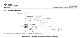
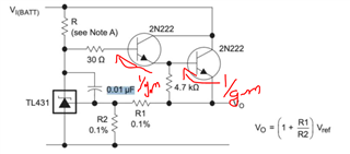
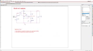
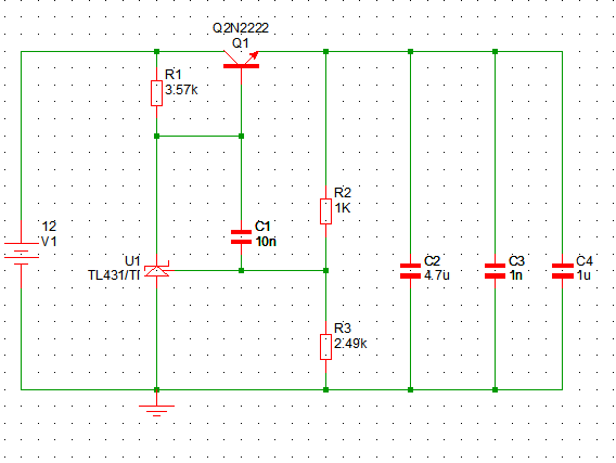
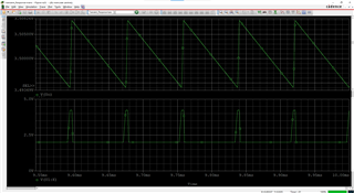
I am using TL431 to build a regulator with max. average load current of 0.5Adc and transient start-up peak current of 2Apk. This regulator is used for power of SiC mosfet driver.

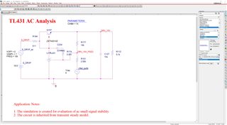
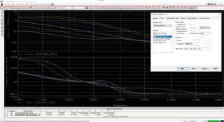
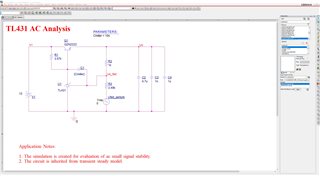
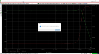
I notice there's a 0.01uF aluminum capacitor recommended in application notes. Normally compensation is necessary when using TL431, but how to evaluate this capacitor?

  • Hi Rookie 

    This is miller compensation. It makes sure that you are in the right side of unstable region with any load capacitor. 

    Regards

    Trailokya 

  • Hallo, Trailokya:

    Thanks for your reply.

    BTW, how can I make sure the capacitance of this "miller compensation" is enough or not? 

  • Hi  Rokkie 

    What is the value of R, R1,R2 in your design and what is your load capacitor at Vo or cathode pin? 

    Regards

    Trailokya 

  • R=511Ω, R1=14kΩ, R2=2.55kΩ, load capacitor is 10uF, parallel with a 5.1kΩ dummy load. The Vin is around 20Vdc while Vo expected to be 16~18Vdc.

    May I ask if there's any calculation method or AC sweep simulation by TINA since we do not know exact small signal model of this product (TL431)

  • Rookie 

    TINA is not modeled for exact stability of the capacitor.  

    If you analyze it's small signal model then you can see VO is connected to cathode with 30 ohm + 2/gm ohm resistor. That will be considered as ESR and you can refer the stability plot for your load capacitor. 

    (Internal gain * 0.01uF) capacitor will come in parallel to that.  

    Your circuit should be stable. You can also refer to app note slva482a for capacitor selection. 

    Regards

    Trailokya 

  • Hi, Rai:

    I download PSpice model of TL431 from TI website and make a transient and AC simulation in OrCAD PSpice. I add small perturbation (Ufed_purtb) in feedback loop(below voltage divider resistor) to do an AC sweep. Then I get gain-phase bode plot, this helps me to evaluate stability of my design.

    According to the AC sweep simulation, It seems that cut-off frequency move left (get smaller) if we enlarge miller compensation capacitor:

    If I choose 10nF for miller compensator capacitor, I get a cut-off frequency of around 3.7kHz and phase margin of around 151degree:

    Do you have any comment. Is this simulation right and advisable?

    Thanks for your attention and hope to see your reply.

  • May I know what is the internal gain meaning? did you mean the Vo/Vin? or the gain(dB) over the frequency?

  • HI Hugo 

    Your analysis is correct. Miller cap will introduce a pole at very low frequency. How ever PM and curtoff frequency may vary in actual frequency. 

    I meant gain (dB) over frequency for internal gain. 

    Good luck with your design. 

    Regards

    Trailokya

  • Ral, thanks for your prompt reply. the simulation was created Rookie but not me, i just the guy who interested with this topic also.

    However, I was measure phase gain in real case and find out when I opened miller cap, phase gain result is good but Vo start oscillation.

    It's makes me confused, did you have any idea on this?

    Desc Phase Gain cutoff freq
    With miller cap 10nF 83.97 deg -6 db 6.21kHz
    Without miller cap 72.96 deg -18.58 dB 6.32kHz

  • What's the ripple or disturbance frequency in output side?

  • I forget to attached the waveforms. The frequency is about 27k~28khz, measured with C1 open condition

    Ch3 output ripple

    Ch4 VkA

  • Hi, Hugo.Yang:

    Below is my AC Sweep loop stability simulation considering C1 (miller cap) = 10nF. The simulation shows when using 10nF, cut-off frequency is around 4.535kHz and phase margin is around 99.63degree, a little different from your first loop measurement.

    And if C1 (miller cap) is removed, I get transient simulation below, which is similar to your waveform measurement.

    But AC Sweep loop stability simulation below is quite different from what you have mentioned.

    It shows that there's no cut-off frequency and relevant phase margin as well. And it seems that there's a pole around frequency 100kHz.

    Is this AC Sweep loop stability simulatoin can explain the oscillation you have seen?

  • Hi 

    The AC input should be given on the REFERNCE pin. I will check in PSPICE and let you know. 

    Also the silicon behavior may be little different from the PSPICE model. So I would suggest to check the pulse response on the real circuit also.

    Regards

    Trailokya 

  • Vref will be influenced by ground perturbation which is injected.
    I agree, check the pulse response on the real circuit.

    Thanks.

  • Hi 

    I m working on Spice model. 

    Regards

    Trailokya 

  • Hello Rai,

    May I know how can calculate the low frequency that miller cap introduced? it is can be seem as  Wp = 1 / (R1*Cmillier) ? 

  • Hi Hugo

    R1 is not a published information so I can't share that on public forum. 

    Also the circuit which you bare simulating is different from the one published in the data sheet. You need to adjust the load capacitor to make it stable.

    Couple of suggestions for stability check -

    • Make sure the output is stable before taking the BODE plot. When you do a small signal analysis on an unstable DC then it will give you wrong information of the phase margin. That is why you are seeing +ve PM but the output is unstable. 
    • For stability check of the system it is good if you can 
      • Give a pulse (1ms ) on the supply  node and check if the output is stable. 
      • Then check BODE plot.
      • Better to do this analysis over temp. 

    Regards

    Trailokya