This thread has been locked.

If you have a related question, please click the "Ask a related question" button in the top right corner. The newly created question will be automatically linked to this question.

TPS82130: -Ve Voltage issue

Part Number: TPS82130
Other Parts Discussed in Thread: TIDA-01457

Hi

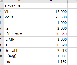
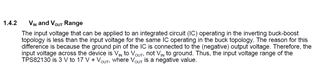
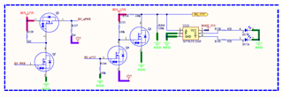
I ran into an issues with TPS82130 used as in inverting configuration in our designed boards as suggested in TIDA-01457. Please see the below schematic. I am using 12V as Vin. we designed 3 protoype boards

1. On one board, I measured the Enable signal @ 12V, yet I don't see any output voltage of 5.5V. I measure it as 0.5V. The voltage at Vfb is measured as 0.4V. I should be measuring the reference voltage of 0.8V correct.

I am not sure what the issue is, is the part not working ?

2. One board works perfectly fine, no issues when we are powering up using a DC-DC power supply for 12V.

3. The other board was working fine, until we plugged into a chassis with 12V power supply. -Ve voltage regulator (TPS82130) input and outputs are shorted, likely toasted. I am not sure of the cause, as the 12V DC from chassis is pretty stable.

Can some one please provide me insights on whats going on with TPS82130 ..

Regards

Venu

  • Hi Venu,

    1. TPS82130 max recommended VIN is 17V. But for your application 12V-(-5.5V)=17.5V. If Vin has some variation or spike, it may damage the device. If Vin=12V, the max output voltage should be 5V. Please try to use Vin=5.5V to see if you have same issue.

    2. TPS82130 the EN pin absolute max voltage is VIN+0.3V, if you separate VIN and EN, you could not violate this spec at any time especially power up and power down sequence. Please measure the waveform for EN_nPWR reference to -5.5V which is device GND. See if it violates the spec during power up/down and other conditions. Please try short VIN pin and EN pin together without outside control of EN to see if it improves.

    3. TPS82130 used as IBB application, VIN=12V, Vout=5V, Efficiency=0.85%, the max output current is around 1.2A,. IBB could not support 5V/3A as Buck converter.

    Hope this helps,

    Thanks,

    Nancy

  • Hi Nancy, 

    Thanks for the details. Vin is referenced w,r,t ground. I can use Vin =5.5V with EN pin still connected to 12V. and referenced to Vout. On the working board this seems to be working. The question is when you say Vin in the datasheet is it reference to device ground ? This is because we two references one being the supply ground and the other being device ground (Vout = -5.5V) in inverting configuration

    I checked the voltage on the En_npwr signal it is measuring 17.5V (EN voltage with reference to device ground, -5.5V, no spikes as I see). I can short it out and see (with it being shorted and Vin = 5.5V, voltage is 11V)

    My current draw is less than 1A, no issues there. 

    How about the PG pin, should I be connecting to 5v5 or is it good as is ?

    The board that is not working could be assembly issue, I am going to reflow and see if it resolves.

    Venu

  • Hi Wenu,

    1. There is an issue if Vin=5V and EN=12V, it will damage the device. You can not use 5Vin, is it possible to lower input voltage from 12V to 11.5V to meet total 17V max recommended Vin? Max Vin is reference to device GND which is -5.5V. The Vin max=12V-(-5.5V)=17.5V>17Vmax. See below.

    2. The working board is ok since Vin absolute max voltage is 20V and it may not damage immediately  and may affect device reliability.

    3. You should not use meter to measure EN_npwr voltage, you need to measure the waveform to compare Vin to -5.5V and EN to -5.5V during power up and power down and other conditions. Zoom in the waveform to make sure no any chance EN voltage is higher than Vin. Please short EN and VIN pin together if power sequence is not a critical requirement. Then you can save all the EN level shift circuit as well. 

    4. PG pin is ok since you have a 2x100k resistors to make it to be half of Vin. PG pin max voltage is 7V.

    5. It is good to know the not working board could be assembly issue. 

    Thanks,

    Nancy