Other Parts Discussed in Thread: BQ25890, GPCCHEM, BQ27Z561
Hi,
BQ27441-G1b is used in my device.
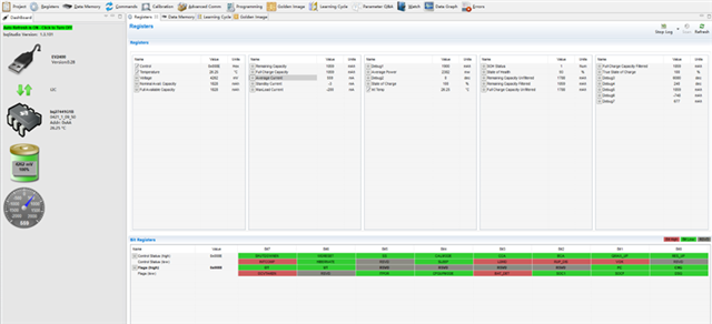
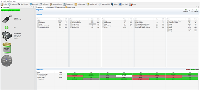
After the battery is plugged in, the following configuration is set to BQ27441 in CONFIG UPDATE MODE.
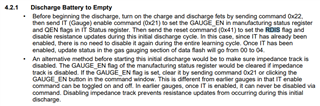
These parameters are learned from following the <bq27441 EVM: System-Side Impedance Track Technology>.
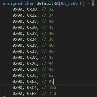
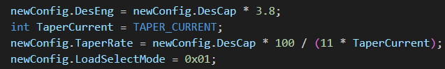
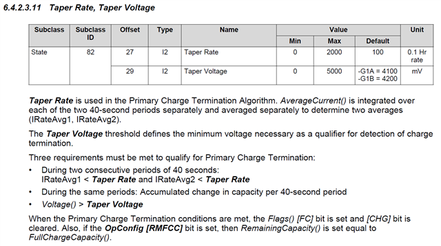
TaperRate = 134.
I am sure all the parameters are set correctly into the BQ27441, because I read the registers out and they are right.
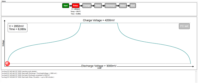
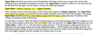
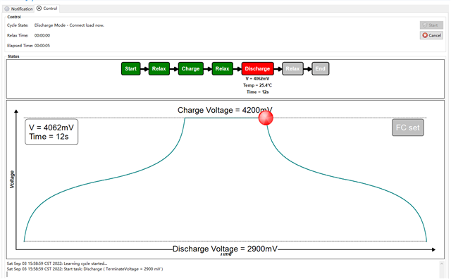
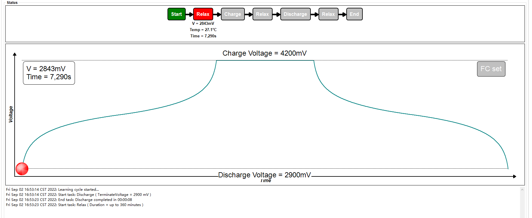
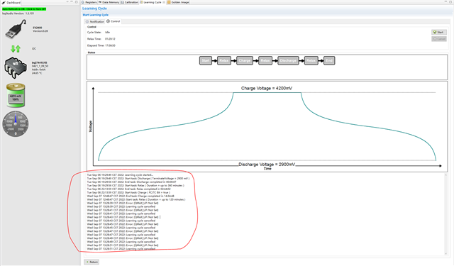
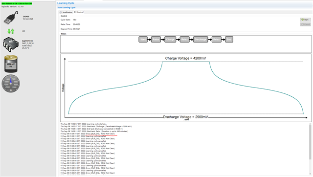
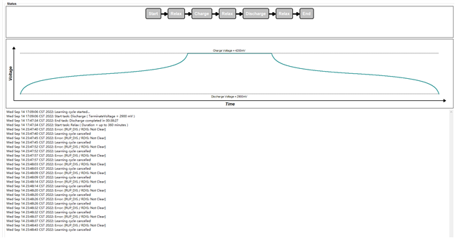
Then, the device is charged and discharged for 3 times:
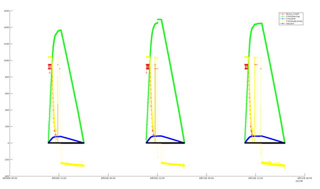
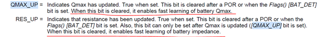
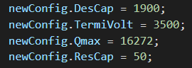
But I find the Qmax/RA is never updated, and the RemCap is around 1300mAH to 1500mAH, far away from 1900mAH, which is wrong.
Why?
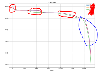
The figure is attached below.
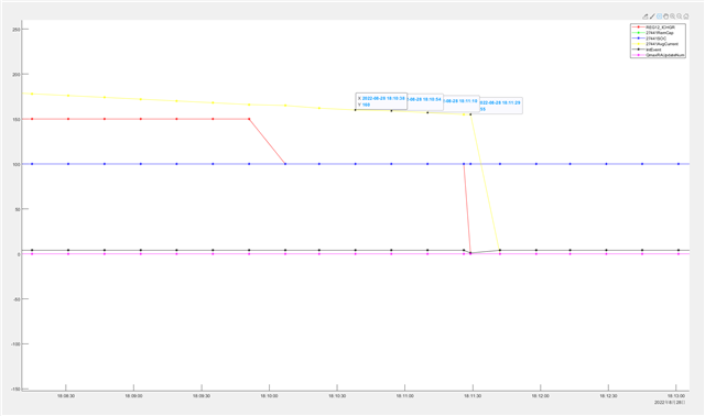
I find that the FC bit is never set to 1 even after the charge termination.
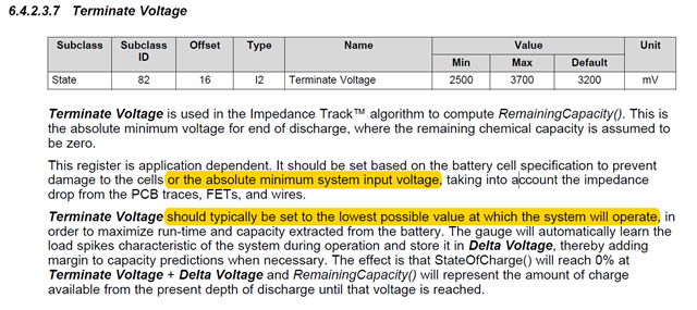
The charging chip is BQ25890, and the terminate current is set to 128mA.
I have read this post:
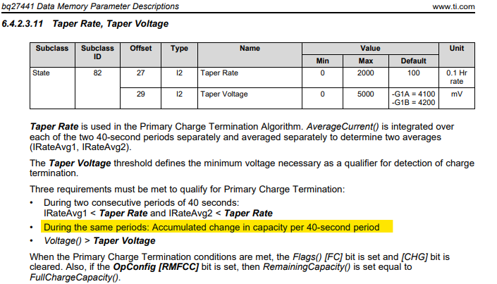
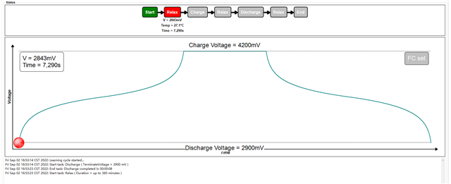
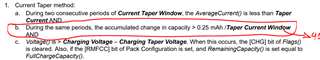
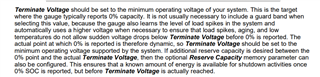
I find the las charging current is 155mA. So it's > Taper Rate(134). So Condition1 and Condition2 cannot be satisfied concurrently.
I'm confused with the Taper Rate.
Taper Rate = 10 * Capacity / TermCurrent =10*1900/128 = 148 Right? Wrong?
But since it's unit is Hr, why compare it with IRateAvg?
What value should I set to Taper Rate in my case, to let FC bit work correctly?
Is it wrong : < Taper Rate and IRateAvg2 < Taper Rate ?
Should it be Taper Current, not Taper Rate?
Thank you.
Frank