This thread has been locked.

If you have a related question, please click the "Ask a related question" button in the top right corner. The newly created question will be automatically linked to this question.

LM5020: Internal Error AMP and SS of LM5020

Part Number: LM5020

Dear sir,

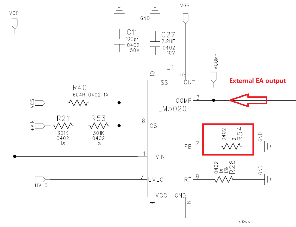
Q1:  on page 7 of 21 in LM5020 datasheet,  it say that the internal errror amplifier can be disabled by connecting the FB pin to GND.  Would you please review the following schematic?
Q2:  During soft start time,  COMP is clamped by SS to conrol the PWM duty.  do you  know what 's the threshold voltage which COMP will take over the PWM control?

Regards,

Jack

  • Hello Jack,

    Thanks for reaching out to us via e2e.

    You wrote:
    > Q1: on page 7 of 21 in LM5020 datasheet, it say that the internal error amplifier can be disabled by connecting the FB pin to GND.
    This is correct.
    By pulling FB to GND the internal error amplifier for the outer voltage control loop can be disabled.
    You can then feed a signal into COMP without driving against the output of that amplifier.
    Instead of the Optocoupler that is used in case of a Flyback, you can also feed an external error signal into that pin.
    But please remember that there is a built-in 5K pull-up resistor internally connected to that pin.


    > Would you please review the following schematic?

    What are the pull-up resistors at the CS pin (R21 and R53) meant for?

    The LM5020 is using a fast (cycle by cycle) inner peak current control loop and a slower outer voltage control loop.
    It is mandatory that the inner current control loop will work properly and the current sense resistor is calculated according to the necessary max peak current.

    Pull-up resistors at the CS pin will disturb the function of the current control loop.
    The CS pin has to be connected to the low side current sense resistor as shown in the datasheet:


    > Q2: During soft start time, COMP is clamped by SS to control the PWM duty.
    > Do you know what 's the threshold voltage which COMP will take over the PWM control?

    There is no fixed threshold voltage for the soft-start pin. Instead there is a voltage delta of 0.55V that goes on top of the voltage on the COMP pin:

    If you define Tss as the time when soft-start begins rising to the soft-start voltage when output voltage hits regulation,
    then what you can approximate it as (Comp + 0.55V)*Css/10uA.

    Best regards,
    Harry

  • Hi Harry,

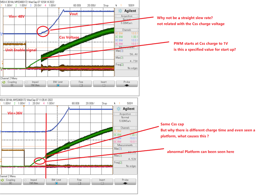
    More detail question of the power-up with Css voltage:

    Regards,

    Jack

  • Hello Jack,

    I am sorry, I don't know all the internals how exactly the soft start mechanism is implemented.

    There are different implementations in different device families, and also different mechanisms which would reset / discharge the softstart capacitor. 

    In general, this soft start feature is only meant to help suppressing a high inrush current.
    I has never been designed to be somewhat precise or linear or exactly predictable and there is no information in the datasheet that would describe that. 

    f you look at the numbers in the table with charge current and offset voltage, you will even end up with 50% tolerance as a worst case.

    The soft start does the job it has been designed for, but it is not very precise.

    Best regards,

    Harry