This thread has been locked.

If you have a related question, please click the "Ask a related question" button in the top right corner. The newly created question will be automatically linked to this question.

UCC28C43: Design help

Part Number: UCC28C43


Hi Team,

A customer designed a schematic using WEBENCH and UCC28C43. 

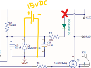
They have encountered an issue that when any load is added, the voltage decreases and only a small current is available in the output. Please see schematic and other information below:

0167.power supply schematic altium.pdf

Primary Voltage 40-350 (DC), Duty Cycle (Maximum) 0.6. I am currently requesting the customer to provide Vds and Vout waveforms.

Please let me know if you need more information.

Thanks in advance.

Regards,

Marvin

  • Hi,

    If any loading causing Vout drop, one often seen cause is the transformer terminal polarities are not connected correctly although the sch shows them correctly - so need to check the waveforms to make sure the winding polarities are correct - need to check on the waveforms as it is possible the drawing the the physical transformer terminals could make difference due to various errors. 

    Second possible and often seen is the snubber values are not correct. To check this, you can use a clamp device like TVS to replace the snubber temporarily so if the TVS can make the converter work while the RCD snubber cannot - it means you need to tune up the snubber. But if TVS still cannot make it work then you will look for some others. 

  • Hi Hong,

    What other waveform do you need to check aside from Vds and Vout waveforms?

    The issue is noticed when the auxiliary diode is disconnected and supply the VCC with external 15V. After checking the voltage on the VDD pin, an 8V is measured even if 15V is supplied with 10 ohm series resistor in between.
    In addition, after the VDD pin is supplied directly without any VCC circuit, the circuit worked well and there is no voltage drop in the output. Kindly refer to the image below:

    Customer mentioed that: "when I connected the supply source after R5 the IC worked very well but when I connected the supply souce before R5 I mesured the voltage across R5 and It is only 8v ! Why that os happening? What exactly R5 resistor does?"

    Thanks for the support.

    Regards,

    Marvin


  • Hi,

    If IC with external 15VDC on the left of R5 can work but not on the right, it means there is some current leaking to cause C14 voltage drops when 15V on the right. 

    R5 is to help filtering out high frequency spikes when using aux winding.

    If your aux winding does not work while external  15V can make the converter work, you need to measure the waveform of AUX winding and compare to Vds to see if AUX winding output waveform is good in terms of timing to Vds and also magnitude. But since even an external 15VDC cannot work when it is at the right of R5, you would need to find what caused 7V drop across R5 from the circuit on the left side of R5. Note R5 does not have to be 10-ohm, it can be less than 10-ohm or even 0-ohm depending on the spikes filtering need. But with a 15VDC you see 7V drop across R5, that it looks to me there is something wrong on your circuit on the left of R5.  

  • Hi Hong,

    The customer finds the issue is coming from the transformer. They replaced it and now the circuit works.

    Thanks for the help.

    Regards,

    Marvin