Other Parts Discussed in Thread: CSD17573Q5B,
Hi,
Is there a specification for voltage drop through body diode? if not, how to calculate it?
Thanks,
Tim
This thread has been locked.
If you have a related question, please click the "Ask a related question" button in the top right corner. The newly created question will be automatically linked to this question.
Hi,
Is there a specification for voltage drop through body diode? if not, how to calculate it?
Thanks,
Tim
Hello Tim,
Thanks for your interest in TI FETs. The body diode forward voltage is specified, 0.8V typ, 1.0V max, in the datasheet at Isd = 40A & T = 25°C. There are also curves of typical Vsd vs. Isd at Tc =25°C and 125°C in Figure 9 of the datasheet. The CSD17559Q5 is an older generation device. We have a newer, more cost effective replacement, CSD17573Q5B, in the same size package with compatible footprint. Let me know if I can be of any further assistance.
Best Regards,
John Wallace
TI FET Applications
Hi John,
Thank you for pointing out the new part CSD17573Q5B, it's a much better part to use and cost effective.
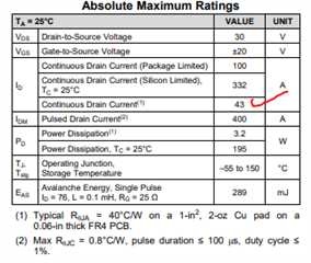
If I use 4 of them in parallel for example, the Id (continuous drain current) would be approx. 172A (4x 43A each), right?

Thanks,
Tim
Hi Tim,
Thanks again for your interest in TI FETs. The maximum continuous drain current specified in the datasheet is calculated using ambient (25°C) & max junction temperature (150°C), junction-to-ambient thermal resistance (40°C/W) and on resistance (at TJ = 150°C) of the FET. Please see the links below for more details on how TI specs maximum current in our datasheets. Actual current capability depends on the PCB layout & stackup, ambient temperature and max operating junction temperature (usually < 150°C for derating). For example, if TA = 55°C and TJ =125°C, the max current is reduced to 32A. With a good layout, you can achieve an effective Rθja around 20°C/W which increases the max continuous current to 44.5A under the same thermal conditions. Another consideration is making sure that the FET operates within the SOA limits shown in Figure 10 of the datasheet. This is primarily a concern when the FET is used in hot swap, battery management and OR'ing applications where the FET controls current at turn on and/or turn off.
https://e2e.ti.com/blogs_/b/powerhouse/posts/understanding-mosfet-data-sheets-part-3
Let me know if I can be of any further assistance.
Thanks,
John