This thread has been locked.

If you have a related question, please click the "Ask a related question" button in the top right corner. The newly created question will be automatically linked to this question.

TL751M-Q1: 12V to 5v, 3.3v, 1.8v, 1.2v, 1.1v schematic review

Part Number: TL751M-Q1
Other Parts Discussed in Thread: TLV767-Q1, TPS7B87-Q1, LM62440-Q1

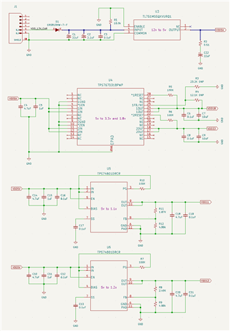
I am working on a new design for an automotive application that requires 3.3v, 1.8v, 1.2v, and 1.1v rails.. can anyone review the schematic below and let me know if there are any concerns?

Input voltage is from a vehicle's 12V system (so, is expected to be in the 11V to 17V DC range).

ICs used are TL751M05QKVURQ1, TPS767D318PWP, 2x TPS74801DRCR

  • U3

    12V down to 5V, thermals will be a concern, adjustment above ambient temperature will be at Iload*Vdrop*38.6 = Iload*(7typ)*38.6 = Iload*270.2, so if operating at ambient temp of 25C, Iload maximum would be 462mA. If operating above this , you may need a device with better thermal performance for this voltage drop, when the VIN can get up to 17V

    everything else looks good.

    U4

    Configured properly

    U5&U6

    Configured properly

    Css is quite large, 15nF is rec max, it is not a problem, however there are concerns with very large Css capacitors if they are not needed.

    Section 7.5.1:

    "The maximum recommended soft-start capacitor is 15 nF. Larger soft-start capacitors can be used and do not damage the device; however, the soft-start capacitor discharge circuit may not be able to fully discharge the softstart capacitor when enabled."

    Regards,

    John

  • Thanks. RE U3, do you have any recommendations for a better part that could handle additional current? Or perhaps adding a heatsink (AL plate?) to the design could help?

    I am still working on the rest of the circuit, so exact loads are not known yet, but some headroom would be nice. (and since this is automotive, I would expect that ambient temp could regularly exceed 25C; 50C-60C would not be uncommon).

    It seems like just switching to the larger 5pin KTT package (Eg, TL751M08QKTTRQ1) would buy me some headroom? (26.5C deg/watt instead of 38.6, = ~674mA max @ 25C ambient?)

  • Hi Adam,

    Yes, switching to the package with a lower thermal resistance constant would have significant effect upon the thermal performance as you've noted.

    The app note linked here also has an explanation of ways that you could improve thermal performance significantly by following a few guidelines in connections and layout. I will hand this over to one of our product marketing engineers so that they can give you the best support on if there are other devices in our portfolio that could meet your needs.

    Regards,

    John

  • Hey Adam, 

    I would recommend the TLV767-Q1 (up to 16V, but with 1A of head room) or we ahve the TPS7B87-Q1 (500mA that goes up to 40V). Let me know if you have any questions on this. 

      TLV767-Q1 TPS7B87-Q1
    AEC Q100 YES YES
    Output Options Adjustable Output, Fixed Output Fixed Output
    Iout (Max) (A) 1 0.5
    Vin (Max) (V) 16 40
    Vin (Min) (V) 2.5 3
    Vout (Max) (V) 14.6 5
    Vout (Min) (V) 0.8 3.3
    Fixed Output Options (V) 3.3, 5, 6, 8, 9 3.3, 5
    Enable YES NO
    Power Good NO YES
    Output Capacitor Type Ceramic Ceramic
    PSRR @ 100KHz (dB) - 70
    Noise (uVrms) 60 252
    Accuracy (%) 1 0.85
    Vdo (Typ) (mV) 800 360
    Iq (Typ) (mA) 0.05 0.017
    Thermal Resistance θJA (°C/W) 52 29.7
    Min Package Area (mm2) 9 19.071
    Package Type SON SO PowerPAD, TO-252

    Thanks, 

    McKyla 

  • Thanks. Looking at my design, I think I might need more power (~2A).

    Do you have any concerns switching the 5V out circuit to a buck converter? Maybe something like LM62440-Q1?

    Not sure if the output would be too noisy for the DS90UH947 and DS90UH948 that will be connected?

  • Hi Adam,

    From the LDO side, there aren't concerns switching to the buck converter. I will move this post over to the team responsible for the 947/948 to see if they have concerns, but one configuration we recommend is placing an LDO at the output of the buck converter, this utilizes the LDO's high PSRR to give a clean output rail for downstream systems, while also giving you the power efficiency inherent to the operation of switching converters.

    Regards,

    John

  • Hi Adam,

    our requirement is to have the Supply noise from DC to 50 MHz below the following:
    3.3V Pins = max 100 mVP-P
    1.8V Pins = max 50 mVP-P
    1.1V/1.2V Pins = max 25 mVP-P