Hello experts,
according to TI website the LM5161-Q1 provides the feature "No External Ripple circuit needed (at FPWM = 0)". Also the datasheet says "When the FPWM pin is grounded or left floating, an internal ripple injection circuit is enabled. With the internal ripple injection enabled, the typical external feedback ripple injection circuit is no longer required." "When the FPWM pin is shorted to ground or left unconnected, no external ripple injection is necessary in a Buck application. Should an external feedback ripple circuit be configured when FPWM = 0, it will produce higher ripple at the output." Unfortunately this internal ripple injection circuit is not shown in the functional block diagram, nor are the parameters of this internal ripple injection circuit specified in the datasheet.
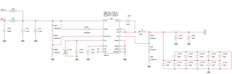
We have configured FPWM to GND for our Buck application. That's why we use a resistive voltage divider for the feedback node. But with an output capacitance of 90 µF with low ESR we are observing unstable switching behavior with multiple ON-time bursts in close succession followed by a long OFF-time. The ripple looks nearly sinusoidal, as described by SNVA166. It seems, that the internal ripple injection circuit is not working properly. We assumed that the integrated capacitance used by the internal ripple injection circuit is too small to forward sufficient AC ripple from the SW output to the FB node. That's why we have increased the impedance of the voltage divider to 330k || 220k = 132k. Without success, the ripple did not disappear. When decreasing the output capacitance, the ripple disappears.
Questions:
1) Is there a design limit for the output capacitance with low ESR when using the internal ripple injection?
2) Are there any restrictions for feedback resistor values when using the internal ripple injection?
2) What is the value of the integrated capacitance of the internal ripple injection network?
3) Where do I find more information about the internal ripple injection circuit?
Regards,
Matthias