This thread has been locked.

If you have a related question, please click the "Ask a related question" button in the top right corner. The newly created question will be automatically linked to this question.

TPS25750: I2Cs_IRQ not pulling low

Part Number: TPS25750

I am using the TPS25750D version of this chip. Pin 10 (I2Cs_IRQ) is not asserting when we connect a charge cable. We want this pin to pull low when a charge cable is plugged in.

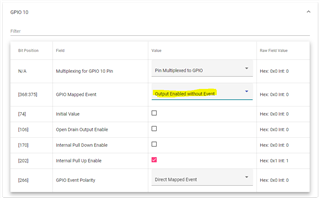
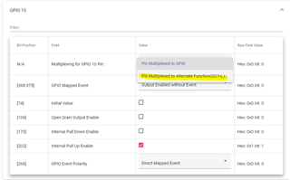
We had the GPIO 10 configured as an interrupt and have the default interrupt events enabled in the advanced configuration tab in the GUI.

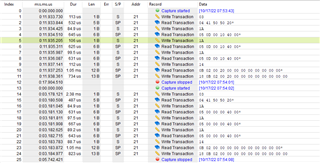
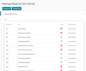
We see the PlugInsertOrRemoval bit in the INT_EVENT register enabled when we plug in the cable, but the interrupt pin stays high. 

We have a 100k pull up to this pin to not keep it floating. 

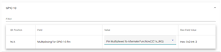
To verify the hardware, we configured the pin as a GPIO and pull low with a plug event. This worked but we need it to be an interrupt pin not a GPIO to detect different events or states of the PD chip. 

We used GUI version 7.0.3 to download the binaries. 

Is there any other special advanced settings we need to configure to properly enable this interrupt pin? 

Could the binary not have downloaded correctly to the configs we wanted? 

Thanks,

Victor

  • Hi Victor,

    Can you capture and share an I2C log of the I2Cs CLK and IRQ line when you plug in/remove the cable? 

    Thanks and Regards,

    Raymond Lin

  • I am helping Victor with this, at his request.  As he mentioned, we're not seeing the I2Cs_IRQ going low when we think we've configured it in the TPS25750 Application Customization Tool.  I wanted to ask some clarifying questions for the tool settings, since they seem unclear to me in spots:

    1. For having the I2Cs_IRQ pin function as an IRQ, what should we have GPIO10 (the I2Cs_IRQ pin) configured as?  I believe it should be "Pin Multiplexed to Altern...", correct?
    2. Neither the TPS25750 Host Interface TRM nor the customization tool seem to indicate the sense of the interrupt mask, INT_MASK1.  In traditional parlance masking an interrupt means it's ignored.  Is that the case for the Interrupt Mask for I2C1 (0x16) setting as well?  If there is a red-checked box in the tool on that page does that mean the interrupt is enabled or disabled?

    Reading from the TPS25750 registers I can see that the chip is in APP mode, and I can see that it's detecting that something is plugged in, or not plugged in, but the I2Cs_IRQ pin doesn't go low.  There is no I2Cs traffic as the plug is inserted or removed, but here is the traffic checking the status (Beagle log):

    Here are some registers read from the TPS25750.

                    MODE 03 ( 4 bytes): 20 50 50 41
     DEVICE_CAPABILITIES 0d ( 4 bytes): 00 00 19 f8
              INT_EVENT1 14 (11 bytes): 00 00 00 00 00 00 00 00 00 00 00
               INT_MASK1 16 (11 bytes): 03 00 00 00 00 00 00 00 30 30 02
                  STATUS 1a ( 5 bytes): 00 40 00 00 20
       POWER_PATH_STATUS 26 ( 5 bytes): 40 00 00 00 00
            PORT_CONTROL 29 ( 4 bytes): 03 81 c0 72
             BOOT_STATUS 2d ( 5 bytes): a1 a2 f0 00 18
          RX_SOURCE_CAPS 30 (29 bytes): 00 00 00 00 00 00 00 00 00 00 00 00 00 00 00 00 00 00 00 00 00 00 00 00 00 00 00 00 00
            RX_SINK_CAPS 31 (29 bytes): 00 00 00 00 00 00 00 00 00 00 00 00 00 00 00 00 00 00 00 00 00 00 00 00 00 00 00 00 00
          TX_SOURCE_CAPS 32 (31 bytes): 00 00 00 00 00 00 00 00 00 00 00 00 00 06 41 f4 00 04 b1 2c 00 02 d1 2c 26 01 91 2c 2a a8 01
            TX_SINK_CAPS 33 (29 bytes): 00 00 00 00 00 00 00 00 00 06 41 45 00 06 41 f4 00 04 b1 2c 00 02 d1 2c 10 01 91 2c 01
     ACTIVE_CONTRACT_PDO 34 ( 6 bytes): 00 00 00 00 00 00
     ACTIVE_CONTRACT_RDO 35 ( 4 bytes): 00 00 00 00
            POWER_STATUS 3f ( 2 bytes): 00 00
               PD_STATUS 40 ( 4 bytes): 00 05 00 00
             TYPEC_STATE 69 ( 4 bytes): 67 00 00 00
            SLEEP_CONFIG 70 ( 1 bytes): 01
             GPIO_STATUS 72 ( 8 bytes): 00 00 00 90 00 00 00 08
    

  • Hi Chris,

    1. Yes you are correct, in order to use the IRQ lines GPIO 10 needs to be reconfigured as shown below:

    2. Let me ask internally to see what the definite answer is. In the meantime, can you try both check and uncheck and observe the behavior?

    Also a new version of the online was just released, you can find the link here in this FAQ: https://e2e.ti.com/support/power-management-group/power-management/f/power-management-forum/1133736/faq-when-i-configured-the-usb-pd-chg-evm-01-using-the-online-application-customization-tool-the-pd-controller-isn-t-communicating-correctly-with-the-bq25792-fixed 

    Thanks and Regards,
    Raymond Lin

  • Not sure if this is fixed in the latest version, but I2Cs_IRQ interrupt seems to be dependent on GPIO10 configuration even if the pin is set to Alternate mode.

    Workaround to try: Enable GPIO10 Open Drain Output and Output enabled without event (and disable pull-ups/downs etc.) before changing it to Alternate mode. This worked for me. If you change it back to GPIO-mode, the UI-elements gets reset and you have to do it again. I also reported this to TI some days ago, but got no response. Very frustrating..

  • Hi Juho,

    Thank you for your response and apologies for your unanswered thread!

    Can you please link the thread that got no response?

    Based on your answer it seems like your issues was resolved, but if you still have any questions please let us know!

    Thank you,

    Kevin

  • By email, to a local contact person.

    But anyway, if this is not yet fixed in the latest configurator version, please fix it.

  • I did have some success getting I2Cs_IRQ to go low.  I tried J.R's suggestion on configuring GPIO10 then switching it to Alternate mode.  That seemed to help.  Can you give some clarification on whether that's needed and when it will be fixed in a release, so you don't need the workaround?

  • Hi Chris and J.R,

    To answer your questions regarding IRQ

    1. To enable the IRQ properly, make sure to set the GPIO Mapped Event first to "Output Enabled without Event", then you can set the "Multiplexing for GPIO 10 Pin" to "Pin Multiplexed to Alternate Function (I2C1s_IRQ)

    Step 1:

    Step 2:

    2. If an event is enabled in INT_MASK1, then it will trigger the IRQ. For example, by default PD Hardreset, Plug Insert or Removal, New Contract as Consumer, etc. will cause an interrupt since they are enabled:

    The IRQ issue has been reported to the GUI engineer and a update will come out soon for this fix. In the meantime, please use the workaround from the first answer (provided by J.R) and this should work. 

    Thanks and Regards,
    Raymond Lin