This thread has been locked.

If you have a related question, please click the "Ask a related question" button in the top right corner. The newly created question will be automatically linked to this question.

TPS63700: Startup problem

Part Number: TPS63700

AS we discussed in our previous Case CS1046835, we've seen many problems during the power-on phase of this device.

Following TI suggestions for Case CS1046835, we've modified the circuit providing the enable introducing a delay, but our problems were only partially solved.

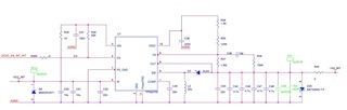
In our application (see attached circ.jpg image) we have a simple 5V to -15V inverter.

In our opinion, the problem is related to the startup current required by our load (we can roughly model our load with a simple RC circuit, where R=12ohm and C=88uF).

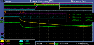
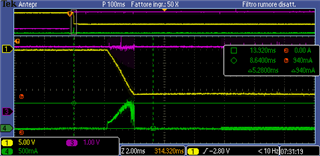
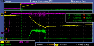
We've measured the current from the SW pin (green trace) with (load.png image) and without(no_load.png) the RC load.

In the same vaweform we show the -15V output (yellow trace) and the 5V input voltage (purple).

Looking to the 'load.png' waveform, after 2ms (maybe a soft-start time) the current reach a maximum limit and then after 8-9ms the dcdc stops switching. 

My main questions are the following:

1) at point 7.4.1 the datasheet is not clear, since there are no data about the soft-start. Which is the duration? How the limitation works?

2) The datasheet never talks about an overcurrent limitation on the output side (in table 6.5 we've only found a reference to an Ilim value). Does the TPS63700 support this king of protection? If yes, how does it works?

3) is it possible to extend the soft-start time working on the feed-back circuitry? (i.e. adding a capacitor to the feedback)

Do you have any other suggestion to solve this problem?

In attachment you can find the pictures mentioned in the text above.

NO LOAD power on sequence

LOAD power on sequence

Thanks and best regards, 

Fabrizio Lucini

  • Hi Lucini,

    The expert supporting this part is on holiday leave. He will reply you after next week. Thanks.

  • Hi  Fabrizio,

    sorry for the delay because we are on our national holiday from 10.1-10.7.

    during soft-start, the current limit will ramps to its nominal value slowly, about the value of ramp, i am sorry, i do not have the date also.

    the current of internal mosfet is sampled and once the current hits the value of limit, mosfet will off and indctor current decrease by charging the output cap.

    i am not very sure, but i think a simple way is to increase your C40 to 1uF and try again. 

    Regards

    Tao

  • Hi Tao,

    thank you for your reply.

    We modified C40 and now the startup sequence seems always good. We've performed a few tests at 10°C and -5°C in order to be more confident, but everything seems to work. We'll perform some further tests in the next days, but we assume this could be a solution for our problem.

    In the following pictures you may see the waveforms.

    • CYAN= 5V input (VCC_IN)
    • YELLOW=-15V output (-15V_INT)
    • PURPLE= ENABLE (EN)
    • GREEN= LOAD CURRENT

    We have two questions for you in order to understand the behaviour of the TPS63700:

    1) looking to the first picture, you may see a long delay (>150msec) between the rising edge of the enable signal and the beginning of the ramp of the -15V output. Standing to the modification we made on C40, we didn't expect a delay but a modification of the output current waveform. Could you please explain this effect?

    2) a few days ago, waiting for your reply, we tried to modify the feedback network in order to increase the time constant of the closed-loop response and therefore to reduce the peak current during startup. For doing this, I placed a 22nF capacitor in parallel to R37 and I removed C38.  Dispite my expectations, the power-on transient was not affected by this modification. Could you explain this behaviour? Do you think this kind of change in the feedback network could be helpful for this circuit, in order to slow down the current transient?

    Thanks,

    Fabrizio

  • Hi   Fabrizio,

    thanks for your work, good to hear it works.

    for Q1, yes, you are correct, C40 has no infulence the delay. but for most device, there always has a delay between EN high and first switching pulse. i think this delay has no matter with C40 and you can try different value of C40 to confirm.

    for Q2, good try, actually, i thought that should be another solution before Joy. but i give up this because the positive input of EA internal is GND.  although with a Cff(22nF in your bench), output of EA still will be high clamped quickly. so it is not a good idea. i think with this Cff, the rising slope of output not change so much, right?

    Regards

    Tao