


Below is a schematic of design I've created using the MC33063A chip. I am have trouble with Q1 (circled in red) when I use a certain part, and I can't quite understand why.
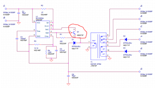
As a little bit on the theory of operation - I am regulating the voltage at J3 to be -11.667V, using the inverting regulator scheme in figure 7 of the MC33063A's datasheet (rev N). I am then using a transformer to generate other voltages: -25V at J2, -32.5V at J4, and 5.4Vrms AC across pins J5 to J7. The loads for these are in my customer's device. For J2, it's 1.61kohm in parallel with 33uF (15mA); for J4, it's 3.57kohm in parallel with 33uF (9mA); For J5-J7, it's 35 ohms (153mA). There is also significantly more input and output capacitance than C1 and C4 would indicate, but it is in my customer's device, so it's not shown here.
I am in the process of updating my company's board from a Through-hole design to a purely surface mount one for manufacturability reasons.
In the original design, we used a ZTX853 npn transistor. (https://www.diodes.com/assets/Datasheets/ZTX853.pdf)
In my updated design, I wanted to go with a ZXTN25100DFH npn transistor. (https://www.diodes.com/assets/Datasheets/ZXTN25100DFH.pdf)
My design works fine with the ZTX853, but when replace the ZTX853 with the ZXTN25100 (keeping all other components and PCB the same), the transistor smokes. I'm somewhat at a loss as to why that happens. The new part has a lower current rating (2.5A vs 4A), but I'm only measuring about 1A peak through the transistor, so I don't think it's a current rating issue. I know I could ship the part using the old transistor, but that would hinder the goal of keeping everything SMT. I could also find a more robust SMT transistor, but I would prefer to understand the reason for the failure before going that route.
Any help or thoughts would be appreciated.
Thanks,
Joe Fledderman
