


Other Parts Discussed in Thread: BQ25180,
Hello, I designed a custom board using the BQ27320 and a BQ25180 as BMS. I am monitoring some strange behavior in my board and can not find where the problem might be.
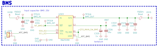
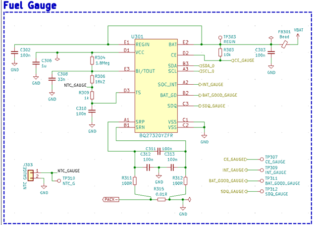
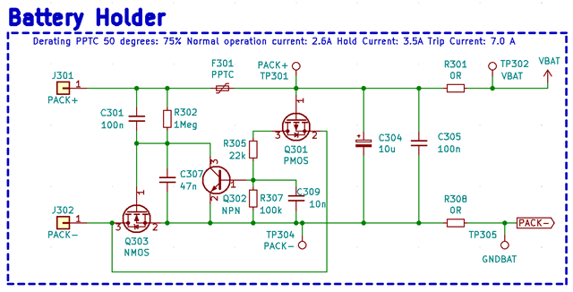
A USB is used as charger, which goes to the BMS that charges the battery. There is a Reverse Voltage circuit with some mosfets just after the battery and then VBAT (after-mosfet) goes to the Gauge and to the BMS. PACK - is also protected by a MOSFET and then goes to the sense resistor after which my main GND for the full Device is generated. Attached you will find schematics for everything.
I am having strange issues when charging the Device. When I plug the Battery into the Evaluation Module for BQ27320 and connect the LOAD output to my Power Input (PACK+, PACK-) everything seems to work. I am able to charge the battery, monitor the current and use my Device perfectly.
But when I disconnect the EV Module and plug the battery into my Device, the battery won't charge. I used some wires attached to my I2C line and ground so I can monitor the behavior of the Gauge from BQ Studio. I am able to calibrate the Gauge from there and it measures current consumption and voltage perfectly. But when I attach the USB, the charging is not detected and the battery is not charging.
I think that the BMS and the reverse voltage protection are not the problem because I am able to charge the Battery when I use it out of the Device with the Ev Module.
Battery is not charging when I don't use the BQ Studio in case you were thinking that maybe the I2C is causing some problems.
Can you think of what mistake I might have made? If you need more info/ schematics /pictures please let me know.
Thank you.
