This thread has been locked.

If you have a related question, please click the "Ask a related question" button in the top right corner. The newly created question will be automatically linked to this question.

LMG1210: Gate signal rise/fall time too long

Part Number: LMG1210

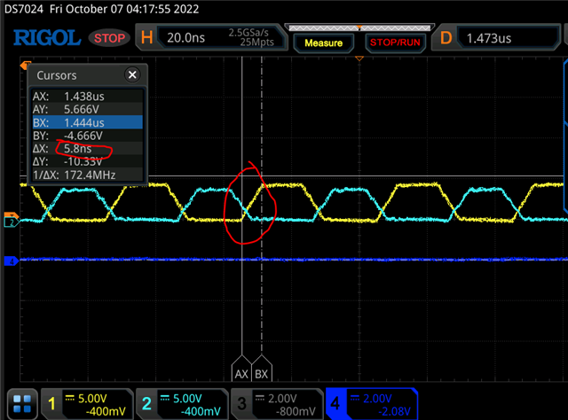
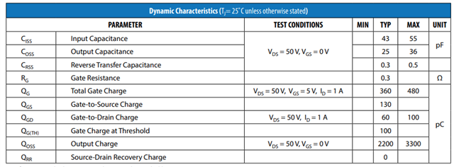
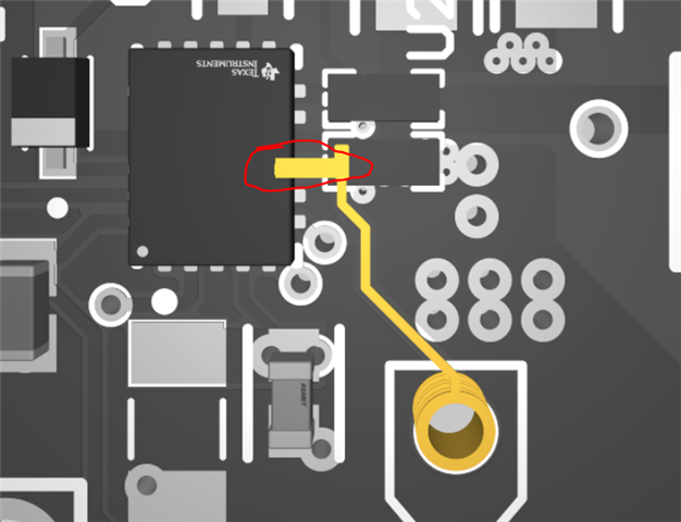
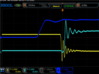
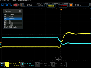
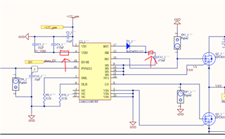
In our design, it is Hbridge GaN EPC8010(Ciss=43pF), gate driver LMG1210. The trace from gatedriver to EPC8010 is super short as shown in attached photo, there is no gate resistor in between. There is trace to a hole/via for probing(same footprint as in LMG1210EVM). So the rising/fall time should be within a ns, while we measure 6ns, as shown in the scope trace. Can you help me diagnose what is going on?

  • Hi Shengnan,

    Yes, I can help with the diagnosis. Your signal path looks good.

    Can you you set your channel bandwidth to Full If there is an option on your oscilloscope?

    You might need a higher bandwidth oscilloscope to measure the rise time. The bandwidth for the Rigol DS7024 is only 200 MHz. As a rule of thumb, you can work out the bandwidth needed with the formula Bandwidth = 0.35 / Rise time. Using this formula, I got a bandwidth of 100 MHz for the loaded rise time.  You then need to have a bandwidth 3 to 5 times greater to capture the true shape of the signal.

    Also, for your oscilloscope, is the 2.5 GSa/s sample rate shared among all channels or does every channel have a 2.5 GSa/s sample rate?

    Best Regards,
    Ethan Galloway

  • Thank you. I noticed there is a big difference in 'acquisition', which one gives me more fideliy?

  • Shengnan,

    You'll want to use normal mode for the signal. Peak mode might also work, but my oscilloscope doesn't have this mode so I haven't tried it before.

    High Res mode improves the resolution and noise at the cost of bandwidth. I don't think this will be helpful.

    Average mode averages the signal across multiple passes. This will decrease the noise in the circuit, but won't give us more resolution.

    By the way, DSO724 calls the "Channel Bandwidth" the "Bandwidth Limit". You can apply the Bandwidth Limit on a channel to reduce the amount of noise you see, but Bandwidth Limit attenuates high frequency signals. You'll want this disabled, but it looks like you already have it disabled.

    Best Regards,
    Ethan Galloway

  • Thank you very much for your quick response. I am able to measure properly as shown.

    Deadtime set to 2ns, switching frequency is 25MHz. There are quite big of oscillation at both turning on and turning off. The oscillation causes shoot through, when DC link voltage is applied on the Hbridge. When I check the demoboard, gate drive signal is very clean(second waveform). According to  the schematic of the demoboard, gate resistance is 0. Compare my board to demoboard, the GaN on my board has much smaller gate capacitance(43pf vs 700pf), the gate loop is smaller. So i am wondering what is the magic with the demo board that has no oscillation? how can i tune my board?

     ET_LMG1210_EPC8004.PcbDoc

  • Hello Shengan,

    The lower capacitance is increasing the ringing compared to the demo board. This is because there is nothing in the circuit to damp the signal. To decrease the ringing, I would recommend adding in a gate resistor or changing to a FET with a higher gate capacitance.

    If you don't add in a gate resistor, I would recommend adding a gate resistor placeholder.

    Best Regards,
    Ethan Galloway

  • Hi, In my case, with small gate capacitance there are quite some ringing with the gate voltage, while there is no space to put in gate resistor. Is putting a few Ohm in series with the decoupling cap too stupid idea? Since the peak gate current comes from the decoupling cap, can this limit the peak charging current?


  • Hello Shengan,

    That method should work to slow down the signal rise time, but it won't slow down the signal fall time.

    You could try putting capacitors from HO/LO to HS/VSS. This would slow down the rise time and dampen oscillations. The capacitors should be as close as possible to HO/LO, but the test point you have on the board might be good enough.

    You could also try going to a FET with a higher capacitance.

    Let me know if you have any more questions.

    Best Regards,
    Ethan Galloway

  • Thank you very much for your help