This thread has been locked.

If you have a related question, please click the "Ask a related question" button in the top right corner. The newly created question will be automatically linked to this question.

TPS74701: How to use TINA to simulate the loop of LDO

Part Number: TPS74701

Hi team,

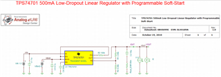
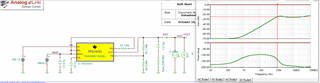
We are using TINA for LDO simulation.

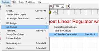
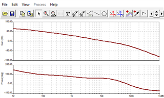
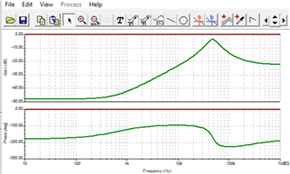
But we use AC analysis, can not get the correct BODE map.

We want to simulate the loop of the LDO through this.

slim253.tsc

Do I need to modify the default use case? Still need to make corresponding settings?

Thanks,

Xiaoxiang

  • Sorry, the picture is wrong, this is the picture. Doesn't look like LOOP BODE.

    Thanks,

    Xiaoxiang

  • Hi Xiaoxiang, 

    Are you trying to simulate Open Loop Gain? i.e to obtain phase and gain margin? or is it PSRR plot the goal?

    I'm afraid our TINA models do not have a very accurate model of the real internals of out LDOs. 

    I would encourage trying to play with some of the parameters as I noticed that some of the parameters do not match those seen on DS, like Vin, Css to mention some

    Notice that I changed the current to 500mA, input voltage to Vin=1.8V and Css to 1nF and the bode response is different now. 

    Best, 

    Edgar Acosta