This thread has been locked.

If you have a related question, please click the "Ask a related question" button in the top right corner. The newly created question will be automatically linked to this question.

UCD9090: GPIO PMBus write Ignore

Part Number: UCD9090

Hi Sean,

I am posting this in behalf of our customer. Kindly please help.

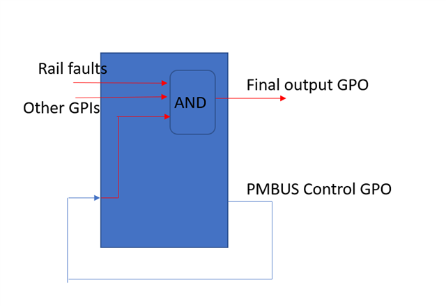
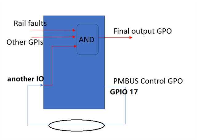
Is there a way to configure a GPO in UCD9090, such that depending on state of internal logic, it ignores a logic change command issued over PMBus? For example, if there is a fault, or a GPI is low, it keeps the GPO at logic low, despite a PMBus command to change to logic high. But if no fault exists, or that GPI is a high, the GPO state can be written as either low or high over PMBus. 

Best regards,

Jonathan

  • Hi

    Logical controlled GPO and command controlled GPO are independent.

    Could you please explain the background for this so that we can see whether there is better solution?

    Regards

    Yihe

  • Hi Yihe,

    Thanks for responding. We have a requirement to control logic state of a GPO via PMBus, but qualified by UV/OV no fault. To be more specific, GPIO2 is configured as a GPO, and its state needs to be controlled by SW over PMBus. However, if there is a rail fault, the GPIO2 output must stay as logic 0. That is, if SW writes a logic 1, that should be ignored.  

  • Hi

    The only way I can think is to let the software to control another GPIO Pin, which loop back to another GPIO on the UCD9090.

    So you configure the targeted GPO to be AND gate of all input. so when there is a fault, the command GPO does not make impact on the output. when there is no fault, the output is controlled by the command GPOs

    Regards

    Yihe

  • Thanks. I will look into that. We will get the SW to not control the target GPO directly, but to control the interim GPO. The interim GPO will be gated by fault etc. 

    Regards

    Mansoor

  • Hi Yihe,

    So I set up GPIO11 as a GPI (not as GPO), then used it to feed into the existing gating logic. I put an external pull down resistor on GPIO11 to establish a default state at power up. The solution works as expected. That is, with no fault condition and other HW signals in favorable states, writing a low to GPIO11 changes final GPO to low and writing a high to GPIO11 changes the final GPO to a high. 

    Just wanted to confirm, since I used GPIO11 as a GPI (not as a GPO), will this cause any problems? The datasheet only specifies that a GPO can be toggled via SW, but it does not elaborate if a GPI can be SW controlled. 

    Thanks

    Mansoor

  • HI

    When a pin is named GPIO, it means that this pin can be either a GPI or GPO. 

    When a GPIO pin is configured as GPI, you can not use the pmbus command to let UCD to toggle it. 

    But you can use any external way to control that GPI.

    Regards

    Yihe

  • So even if it works when configured as GPI, it cannot be relied upon. Is that what you mean? 

    I say that because I have it working as such on my test board.

  • Hi

    What I am saying is that GPI or GPO is just up to how you configure the pin.

     What you test is right to approve the concept.

    Regards

    Yihe 

  • I agree. Conceptually, a GPI would not be needing to be toggled via PMBus command since it is an input. Interesting enough, after I configure GPIO11 as GPI, and use PMBus to toggle its state, I can measure on physical pin 16 of the device as 0V or 3.3V, depending on what I wrote via PMBus. 

    My reason to configure the interim pin as GPI (instead of GPO) is that I have already used up first 8 GPOs. As per datasheet, a 9th GPO cannot be used in internal boolean logic. 

    Do you think there is any kind of risk in relying on a PMBus command to toggle a GPI pin logic state? 

  • Hi

    when you use the PMBus toggle a pin configured as GPI, you essentially reconfigure the pin from GPI to GPO. that's why the output is changed.

    For this proposal, you are not adding any new logical controlled GPO.

    The first 8 logic controlled GPO can be as input for the logic, but pmbus control GPO does not count. why do you need 9th logic controlled GPO here? 

    Regards

    Yihe 

  • When attempting to setup boolean logic for 'Final output GPO', there is a preset list of GPIs, and GPOs. If I do not set the 'PMBus Control GPO' as a logic controlled GPO within the first 8 GPOs, or first 8 GPIs, I cannot use it in the boolean control logic of 'Final output GPO'. 

    For example, consider the system below. Here, if I want to use GPIO17 in the boolean logic of  LGPO #10, I cannot use it unless GPIO17 is defined as either a GPI or a GPO. 

    Furthermore, it needs to be defined within the first 8 of either GPI or GPO.

    I may be missing some trick as this is my first project with UCD9090. Let me know what you think. 

    Thanks

    Mansoor

    PS: Updated the first image to include GPIO17, which was defined as command controller GPO. It was cropped in the previously uploaded capture. 

  • Hi

    Did you use all 8 GPIs? You can not use the GPIO17(configured as commanded based GPO) as input to a logic GPI unless the GPIO17 is physically connected to other pins. 

    What I proposed is to let the GPIO17 physically connected to one of the GPIO pin which shall be configured as GPI function.

    Regards

    Yihe

  • I guess I did not specify before that we do not have a possibility to change the board level design and to rev the PCB. Any change must be in UCD9090 programming only. 

    Coming back to configuring a GPIO as GPI, using it in boolean logic of 'Final output GPO', and letting SW to toggle that GPI via PMBus, if this is not recommended, then I must look into moving things around in the first 8 GPO listing. 

  • Hi,

    It was not specified that you have the hardware fixed.

    Let me summarize what you plan to do

    1. currently, GPIO11 is configured as logic control GPO

    2. you will remove GPIO11 as logic control GPO and configure it as GPI, and feed it to your final target GPO

    3. you use the pmbus command to change the GPIO11 to either output high or low

    It will work but what's your initial state of GPIO11 when the UCD is power up?

    Regards

    Yihe

  • Nice summary! Yes. That's what I plan to do. The initial state of GPIO11 must be low. I have an unpopulated pull-down 0402 on the board. So as part of my change, I will also populate a 4K7 to pull the GPIO11 down. This will be a BOM change only. What do you think?

  • Hi

    Yes, it shall work.

    Regards

    Yihe

  • Beautiful! Thanks for helping out. 

    Regards

    Mansoor

  • Hi

    Thank you. This threshold is closed.

    Regards

    Yihe