This thread has been locked.

If you have a related question, please click the "Ask a related question" button in the top right corner. The newly created question will be automatically linked to this question.

UCC21750-Q1: How to use bootstrap method with UCC21750-Q1?

Part Number: UCC21750-Q1
Other Parts Discussed in Thread: UCC14240-Q1

Hi,

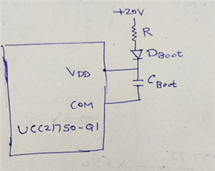
How to use bootstrap with UCC21750-Q1?

There is no separate boot pin to connect boot capacitor.

Pinout - 

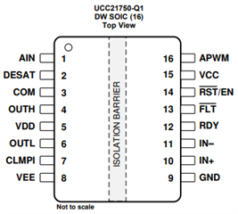
Can we connect boot capacitor to VDD pin?

If possible pls share ref. bootstrap design for UCC21750-Q1.  

  • Hi Abhishek,

    The Bootstrap circuit can be used to generate high side isolated bias, but with bootstrap circuit you can not generate negative bias using Zener. You have to use VEE=COM. The boot capacitor will be connected between VDD pin and COM pin.

    There is no bootstrap reference circuit available for Jolt. However you could refer the bootstrap circuit given in the UCC2154x device datasheet  -It is a dual channel device - so one channel is considered for high channel and is planned with a bootstrap circuit and then another channel planned for low side, so no isolated bias needed.

    There are examples shown for how to generate negative bias using Zener as well - but then it can not be used with a bootstrap, only with an isolated bias. Hope it is answers your question.

    Thanks

    Sasi

  • Thank you Sasikala,

    1) You meant to say bootstrap cap can be connected as below -

    Can you please confirm above.

    2) In the power rating section for UCC21750-Q1 as below

    It's mentioned that -

    "Max power dissipation by transmitter side = 20mW"

    "Max power dissipation by receiver side = 965mW"

    I have query that which is microcontroller side power dissipation & which is MOSFET side power dissipation?

    Is transmitter side = MOSFET side & receiver side = Microcontroller side??

    Regards,

    Abhishek D.

  • Hi Abhishek,

    • Yes your bootstrap cap placement looks right.
    • Transmitter side is  the u-controller side.
    • Receiver side is the MOSFET side.

    Thanks

    Sasi

  • Hello Sasikala,

    We are using SiC MOSFETs having gate voltages +15 & -5V.

    Can we use negative supply for Bootstrap MOSFET driving method while using UCC21750-Q1?

    Regards,

    Abhishek Deshmukh

  • Hi Abhishek,

    The Bootstrap circuit can be used to generate high side isolated bias, but with bootstrap circuit you can NOT generate negative bias using Zener from the bootstrap bias.

    If you are planning to use a separate isolated negative bias for negative supply and the bootstrap for the positive supply.  Then, Yes you can do that.

    Please press "Resolved" if it answers your question.

    Thanks

    Sasi

  • Thanks Sasikala,

    But during turn off when negative bias is applied to MOSFET gate (through OUTL pin), that negative bias is also applied to gate driver OUTH pin.

    Is it OK to make such connection? Or any protection needed here?

    Regards,

    Abhishek Deshmukh

  • Hi Abishek,

    Yes the Gate will be exposed to Negative bias voltage [-5V]. The OUTH can withstand the VEE bias supply. Please check the Abs max limit for OUTH.

    However, I am curious to understand, why would you plan a separate bias for negative bias and then a bootstrap circuit for positive bias. We have a reference design using a single chip solution which will work perfect along with UCC217xx part to provide both positive and negative isolated bias.

    It saves space, time and as well proven solution.

    Please check the following reference design.

    Please let me know if you (and team) are interested in the solution.

    Also interms of using Bootstrap circuit + isolated negative bias, you may have to simulate to ensure that the corner cases are planned as I couldnt find any reference design with both of it together. It will be good to simulate to understand the performance for all the system needs.

    Thanks

    Sasi

  • Thank you.

    I checked your suggested solution, but its input range is between 21 to 27V & we have fixed 12V supply.

    So this solution is not suitable for our application.

    Regards,

    Abhishek D.

  • Hi Abhishek,

    Let us reach out to the product line that owns the UCC14240-Q1 device to see if they have a solution in the UCC14xxx family that could fit your application. We will provide a update when we get a response.

    Best regards,

    Andy Robles

  • Hello Andy,

    Our range is 9 to 16V, we have buck boost converter that will regulate input (9 to 16V) to 15V & 20V as required by SiC MOSFET gate.

    The input range of UCC14240-Q1 is from 21 to 27V & output range is 18 to 25V

    So this part is not suitable for us.

    Regards,

    Abhishek D.

  • Hi Abhishek,

    I am closing this thread as we are working through emails to find suitable isolated bias options.

    We can create a new thread or reopen this thread if there are more questions.

    Thanks

    Sasi