


Hi,
Good Day.
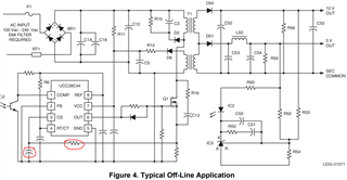
On the component datasheet, an example application schematic (sheets 9 & 10 – Figure 4) shows an RC circuit (see circled in red below) implemented between the Current Sense pin (#3) and the Primary of Transformer T1.
The customer is using the UCC28C45MDREP in a circuit without this RC and is nothing an inconsistent charging current.
- What is the design intent of this RC network on the CS pin?
- Are we damaging the PWM controller without this RC network in our device?
Please advise. Thank you very much.
Best Regards,
Ray Vincent
