Hi,
I saw this design and was going to use it for my design. I have a few questions on how this was designed
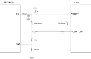
It uses the TPS7H4001 device and I am interested in the remote voltage sensing. The load has output VSENSE and VSENSE_GND pins
Here is the circuit and my questions follow:

Question as follows:
1) I assume the 50 ohm to GND to the PH pin side is for making 50 ohm board measurements of the voltage?
2) What are the purposes of the two 0 ohm resistors? I am guessing they would be changed to a different value if needed once the board gets tested but not sure what would dictate that.
3) What would be the purpose of these large resistors? I know they are not populated but am guessing someday they might?
Thanks!

