This thread has been locked.

If you have a related question, please click the "Ask a related question" button in the top right corner. The newly created question will be automatically linked to this question.

TPS7H4001-SP: Trying to figure out this remote sensing circuitry and whether it make sense

Part Number: TPS7H4001-SP

Hi,

I saw this design and was going to use it for my design. I have a few questions on how this was designed

It uses the TPS7H4001 device and I am interested in the remote voltage sensing. The load has output VSENSE and VSENSE_GND pins

Here is the circuit and my questions follow:

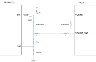
Question as follows:

1) I assume the 50 ohm to GND to the PH pin side is for making 50 ohm board measurements of the voltage?

2) What are the purposes of the two 0 ohm resistors? I am guessing they would be changed to a different value if needed once the board gets tested but not sure what would dictate that.

3) What would be the purpose of these large resistors? I know they are not populated but am guessing someday they might?

Thanks!

  • The engineer that supports this device is out of the office at the moment.

    However, to help answer this, it would be beneficial to know where this schematic originated?

    Without the voltage rail connected to the feedback divider, this cannot work.  Possibly I am missing some context.

    Regards,

    Wade

  • Hi,

    We got your questions and will respond when we return to the office next week.

    Thanks

    Christian

  • Thanks Wade - appreciate you letting me know. As for your question is concerned, I am not sure I follow you. The PH output is connected to the Rtop resistor and then to the Rbottom resistor and sense pin.

  • I apologize and agree with you.  I am not as familiar with the remote sense.     I will let Christian follow up with you. 

  • Hi,

    Can you please let me know from which document you got this schematic as I don't recall having created this.

    Thanks

    Christian

  • Hi,

    This wasn't from TI. It was an old schematic from a program from my company. The designer is no longer here and I am trying to figure out what those added resistors are from.

    Thanks,

    Jeff

  • Hi Jeff,

    Well, I was hoping you would give me a TI document # so I could track down the author and ask that exact question.  But seems the document came from your side. The only thing I can think of is for opening the loop in order to measure the frequency response.  On all our EVMs, the resistor closest to the LC output is typically installed with a 0-ohm resistor.  When measuring frequency response this resistor is lifted and injection and receiver points are on each side.  I suspect the other resistor added near the FPGA is to do the same measurement closer to the load to include the entire loop.  As for the value of 953K it is suspiciously the same value as the slope compensation resistor RSC.  Perhaps the engineer just copied this component in order to have a 0805 footprint placeholder-pure speculation.  No idea why there is 50-ohm resistor to ground on the VOUT node.

    Thanks

    Christian

  • Hi Christian,

    Sorry for dragging you down in this mess! I did find someone who was involved in this design (thought they all left the company). Anyway here is his answers:

    1) The 50 ohm resistor is a bleeding resistor. Its purpose is when the device gets powered down the supply will go right down to 0 volts and not stay at an intermediate voltage due to capacitance.

    2) the 953K resistors are in there to switch between remote and local sensing. Remote they are depops and local the one on the left is in but changed to 0 ohms. The purpose of the large resistor is in case manufacturing installs it when they are not suppose to it won't hurt the circuit. The 0 ohms are used for remote and local sensing as well.

    I was wondering now that this is straightened out that I could send you a circuit of mine for you to look over? If so, do you want me to send it here or open a new ticket.?

    Thanks!

    Jeff

  • Jeff,

    Christian is out of the office today, and returning Monday.

    For the circuit review, it would be best to submit a new post.  This will keep the post subject more meaningful.

    Please mark this as resolved to close it out.

    Regards,

    Wade