Because of the Thanksgiving holiday in the U.S., TI E2E™ design support forum responses may be delayed from November 25 through December 2. Thank you for your patience.

This thread has been locked.

If you have a related question, please click the "Ask a related question" button in the top right corner. The newly created question will be automatically linked to this question.

TPS40305: Reverse Voltage at SW Node

Part Number: TPS40305

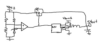
 Hi, we make a buck controller topology in which USB PD input. This means input voltages are 5V, 9V, 15V, and 20V. The maximum current is 5A. We want, if the input voltage is 5V, İnput voltage will directly pass to the output. In other scenarios, the controller going to regulate the input voltages. We editing a topology that contains a comparator and a PMOS load switch for this. If the input is 5V, PMOS is closed and the controller is disabled through the EN pin. If varied than 5V, just the opposite. The issue here is, can the SW node operate at 5V reverse voltage when the controller is disabled? Occur damage of this? (Notice the high side MOSFET's body diode is reverse bias with least -4V)

Thank you,

Best Regards
  •  

    Since the Drain of the high-side FET is also connected to VBUS (5V), the body diode of the high-side FET will not be reversed biased -4V, it will be near 0V with it's Drain and Source connected to nearly the same same voltage.  If you attempted to disconnect VBUS from the drain of the high-side FET,  the body diode of the high-side FET would charge the drain of the high-side FET to about 1 diode drop (0.5 - 0.7V) below VOUT, but since VBUS is still powered to 5V, that is not a concern.

    Yes, this solution would work.

  • Yes, sorry I thought this 0V  bias case but I forgot to write it. In my opinion, the 0V bias of the body diode wasn't enough for it to turn on.

    Thank you so much, Peter. Have a nice day.