


Hi.
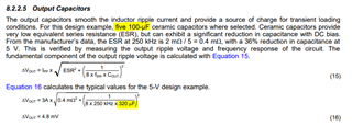
I'm trying to simulate a circuit using LM25116 in PSPICE for TI, but I have some question on how the DS calculate some values. First of all, the input and output capacitor. The DS states that the output capacitors are 5x100uF; however, in the formula shows Cout = 320uF. Why?
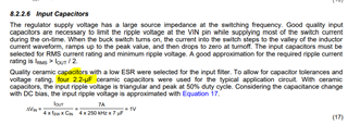
The same way happen to the input capacitor, 4 parallel 2.2uF but they value in the formula is 7uF
My last question is about how is calculate the compensation loop? The DS shows that crossover frequency should be Fsw/10 = 25kHz and since the zero should be less than crossover frequency that's why it is located 2.5kHz. Is it a rule of thumb to put one tenth of the crossover frequency? And then how to choose Ccomp and Rcomp? Because only states "Increasing RCOMP, while proportionally decreasing CCOMP, increases the error amp gain. Conversely, decreasing RCOMP while proportionally increasing CCOMP, decreases the error amp gain" what would be a good error gain Rcomp/RFB2
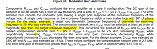
Also, the DS doesn't explain too deep how to select CHF, only shows the second pole location with CHF and that's it.
