Dear team,
Our customer has to adjust the PMIC compensation loop. They see ripple in the 1V line and would like to mitigate it adjusting the compensation loop as well.
They checked an application note SLVA352A regarding the compensation loop and how to calculate the right values for each component, as well as an excel file to calculate the values for the TPS65400, but after calculating the values, I am having more ripple in that line.
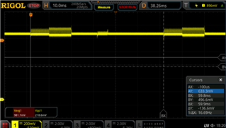
Find attached 2 pics with the results. One is the ripple at 500KHz in the 1V line when RADAR emitting chirps and the other is the ripple in the same line but at 2,1MHz of fsw. As you can see, the “idle” ripple is much bigger at 2,1MHz than in 500KHz…
They also mentioned that the values calculated using the AN and the excel are slightly different; they tried with the values calculated using AN formulas and using Excel but there is not a big difference between them. They wrote: "I can reduce the “big” ripple adjusting the output filter of the pmic, reducing the inductance following the excel guidelines but the idle noise is not reduced at all…"
Could you please help to solve this issue?
Thanks