According to the datasheet, the capacitors are recommended to be tantalum.
For example, on page 12 of the datasheet, the authors suggest using a disc or a tantalum capacitor, "An input-bypass capacitor is recommended. A 0.1-μF disc or 1-μF solid tantalum on the input is suitable input bypassing for almost all applications. The device is more sensitive to the absence of input bypassing when adjustment or output capacitors are used, but the above values will eliminate the possibility of problems." Later, the authors suggest benefits to a ceramic capacitor over a tantalum, "Depending upon capacitor construction, it takes about 25 μF in aluminum electrolytic to equal 1-μF solid tantalum at high frequencies. Ceramic capacitors are also good at high frequencies. However, some types have a large decrease in capacitance at frequencies around 0.5 MHz. For this reason, 0.01-μF disc may seem to work better than a 0.1-μF disc as a bypass."
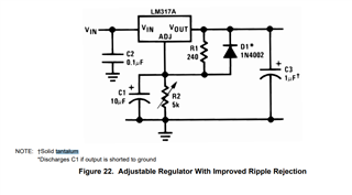
Another example is in figure 22, where the authors suggest making the capacitor on the adjustment leg, and the output capacitor tantalum.
My questions are as follows:
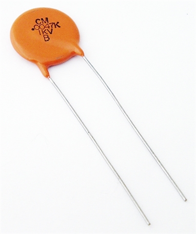
1. What is a "disc" capacitor mentioned by the authors? Does this refer to a MLCC or ceramic capacitor? I am unfamiliar with this terminology.
2. The author indicates a loss of capacitance for ceramic capacitors at 0.5Mhz. If ceramic capacitors are selected to ensure 10uF at 0.5Mhz, would the filtering performance be comparable to using a tantalum capacitor? For example, if I over selected a ceramic capacitance value so that at 0.5MHz, the ceramic capacitor(s) had at least 10uF of capacitance, would this be reasonably comparable? Or is a tantalum required for this application?