This thread has been locked.

If you have a related question, please click the "Ask a related question" button in the top right corner. The newly created question will be automatically linked to this question.

BQ76940: bq76940, cell voltage deviation

Part Number: BQ76940
Other Parts Discussed in Thread: TIDA-010030, TIDA-01093

Hi,

My 11 cell voltages reading from bq76940 and the measured by multimeter comparison

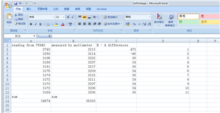
From above you can see the first cell voltage deviation is too large,

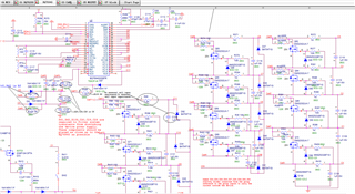
Below i insert  the part of schematic, please help us to identify where the problem is in.

Best regards.

  • Hello Kevin,

    Do you see this deviation in the reading all the time? I notice you use a 1-uF capacitor for your cell input filters, this is a large value that may take too long to settle and cause voltage errors during cell balancing. We typically use smaller values in our reference designs, a value like 0.22-uF. Besides that I believe your schematic looks good.

     If you measure the voltage directly on the VC1/VC0 pins, do you see the same voltage reading? Are you using real cells or a cell simulator?

    If things seem mostly okay, maybe there is a large voltage drop in the ground path to VC1. What is the cell 1 voltage from VC1 to Vss?

    Best Regards,

    Luis Hernandez Salomon

  • Hi Luis,

    Yes, i see this deviation all th time in reading of cell voltages. I use real battery pack of 11 cell blocks.

    I measured the following,

    VC1 to Vss    2793

    VC1 to VC0   2362

    VC0 to Vss   432

  • Hi Luis,

    By the way, we used the circuit from TIDA-010030, the capacitor value is 1uF for the cell input filters.

    Best regards.

  • Hello Kevin,

    Are you measuring with a multimeter? The VC1 to Vss voltage seems correct based on the initial IC measurement.

    I am a bit concerned with the VC0 to Vss voltage being 432-mV, it seems like it is a large voltage drop between VC0 and Vss. BAT- should be referenced to Vss, so the voltage drop here should be minimal. The layout may be causing a large voltage drop causing the inaccuracy of the measurement. Check layout resistances.

    Ground should be connected like shown in Page 4 of the TIDA-01093.

    Since the creation of that TIDA we've found that there are voltage errors in the measurements of the cells during cell balancing due to the long settling time when using 1-uF. We now recommend to use 0.22-uF instead.

    Regards,

    Luis Hernandez Salomon

  • Hi Luis,

    The above voltages are measured by using multimeter.

    Regard.

  • Hello Kevin,

    So you are measuring different values at the pin of the IC and at the cell itself? Then if so, it is advisable that you revise the layout to minimize any resistances that is causing these large drops in voltage. 

    Vss, VC0 and BAT- should all be referenced to roughly the same potential. See Page 3 of the TIDA-00449 schematic for reference in how to tie the BAT-/Vss. I'd also advice to look at the layout files for reference.

    Best Regards,

    Luis Hernandez Salomon