This thread has been locked.

If you have a related question, please click the "Ask a related question" button in the top right corner. The newly created question will be automatically linked to this question.

UCC21750-Q1: If I want to add additional buffer behind ucc21750, what will be the best between BJT or MOSFET as buffer ?

Part Number: UCC21750-Q1
Other Parts Discussed in Thread: UCC21750, UCC27321

Dear expert,

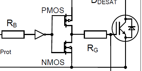
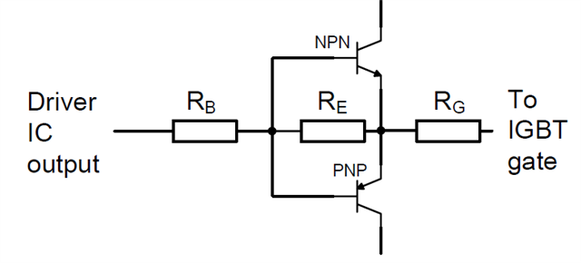
What will be the best structure if my customer would like to add another buffer behind ucc21750 to strengthen the driving ability? 

MOSFET or BJT? And what will be the difference?  

  • Hi Zoe,

    Based on the schematic what you shared, Looks like the power switch is IGBT.

    Can you please share what is the required drive strength and planned bias voltages based on the power switch?

    Please share these additional inputs, I will align with our internal team and keep you posted on the recommendations.

    Thanks

    Sasi

  • Hi Zoe,

    The benefit of MOSFETs is a full rail-to-rail output voltage range. The benefit of BJTs is higher efficiency and output current. However, you could use a "TrueDrive" buffer like UCC27321 which uses both types in parallel.

    Usually the UCC21750 can drive a gate directly. It has beneficial split outputs that would be hard to use if the output is buffered. Larger discrete output transistors might conduct more direct current, but they will not necessarily switch faster, due to larger parasitic capacitance and layout. How large is this IGBT gate capacitor?

    Best regards,

    Sean

  • Sean, Would you please help check below SIC parameters? You mean you didn't recommend additional buffer? Customer is only want to leave this buffer incase larger driven strength is needed. Do you have any proposed circuir? What is your recommendation of gate capacitor? 

  • Hi Zoe,

    Drive strength requirement will be based on the total turn on/turn off losses acceptable to the system and the switching frequency requirement of the system.

    The faster the FET switches, lower losses and the switching speed is directly linked to the driver peak current. UCC217xx driver peak current spec is 10 A , with no external gate resistance. 

    Please refer the following FAQ document which explains how the peak current  and turn on /off time can be computed in a system [It is not for UCC217xx device, but the concept is same]

    We have peak current and power calculation sheet for UCC217xx device in the following link

    Its not a straight forward answer but based on multiple parameters on the system. 

    Please review the FAQ and let us know if you have any additional questions.

    Thanks

    Sasi

  • Hi Zoe,

    The UCC27321 only has a 0.3Ω pull down resistance. However, 4.58uF is a huge capacitor. 

    If you are switching such a large capacitor, you probably need to make a lower resistance somehow. A discrete BJT output stage is one possibility. Parallel gate drivers might be another. 

    Do you have the part number for this SiC switch? What is the target switching frequency? 

    Best regards,

    Sean

  • Hi Zoe,

    Considering the high gate capacitance of the FET [seems higher than typical Gate capacitance] - and may need external current boost.

    Please refer the following application note which talks about different current boost approaches.

    I am closing this ticket for now. We can reopen the ticket or create new ticket for any additional questions.

    Thanks

    Sasi