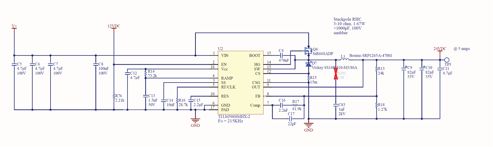
Internal Boot Diode is shorting between Vcc and BOOT pins.
This has happened on multiple boards, after many hours of operation.
Internal Boot Diode is shorting between Vcc and BOOT pins.
This has happened on multiple boards, after many hours of operation.