This thread has been locked.

If you have a related question, please click the "Ask a related question" button in the top right corner. The newly created question will be automatically linked to this question.

TPS548D22: improve transient response

Part Number: TPS548D22

Hi expert,

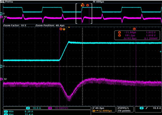
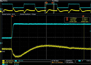
Customer has transient response time requirement that 0-30A, 1A/us, within 100us.

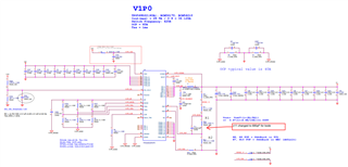
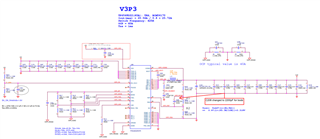
They used two TPS548D22, 1V, and 3.3V, the response time is 192.8us and 326.2us accordingly. 

They are testing different Cff but it may failed bode plot test with small values.  

Would you please suggest what else we can possibly do to improve the response time in the circuit?


Regards,

Allan

  •  

    I would like to understand you and the customer's definition of "Response Time" to better answer the question.

    I am asking because the 1V waveform you provided shows the output voltage recovering to within +/- 5mV (0.5%) of VOUT in approximately 40μs, well below the 100μs specification that was provided while the 3.3V is within +/- 20mV in approximately 60μs.

    With a typical "Recovery Time" specification being the time required for the output voltage to return to with +/- 1% of its final voltage, both are well within the 100μs specification.

    If you can share the BODE plots that you describe, those could be helpful as well.

    However, for the 3.3V design,

    I would recommend:

    1) Removing the Feedforward capacitor (C208)

    2) changing R418 from 4.64kΩ to 110kΩ to increase the reference voltage used on the 3.3V design from 0.6V to 1.1V and R404 from 45.4kΩ to 20kΩ to set VOUT to 3.3V with a 1.1V reference.  This will reduce the feedback attenuation so that the loop is less reliant on the feedforward capacitor to reduce the feedback attenuation at high frequencies.

    3) changing R417 from 4.64kΩ to 12.1kΩ should significantly reduce the initial output voltage deflection and speed up the recovery. 

    Those changes combined should reduce the feedback attenuation from VOUT to FB from 5.5:1 to 3:1 while the increased Ripple time-constant improves the response timing without the need for the feedforward capacitor, whose long time time-constant is slowing the final recovery of the output voltage.

    If the settling time is still not what the customer would like, I would suggest trying to removing 2 of the 100μF capacitors, which will increase the bandwidth and may improve the phase margin, as I am estimating a rather low loop crossover frequency.

    For the 1.0V design,

    I would recommend

    1) Remove the Feedforward capacitor (C11)

    2) Change R4 from 4.64kΩ to 75kΩ to change the reference voltage from 0.6V to 1.0V and change R10 to 0Ω, eliminating the feedback attenuation and the need for the feedforward capacitor (C11)

    If that still does not meet the their recovery time requirements, I would suggest removing the 2x 470μF output capacitors.