This thread has been locked.

If you have a related question, please click the "Ask a related question" button in the top right corner. The newly created question will be automatically linked to this question.

BQ25601D: D+/D- connection

Part Number: BQ25601D
Other Parts Discussed in Thread: BQ25601, , BQ25611D

Hi team,

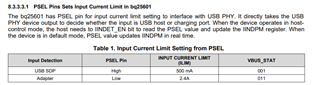
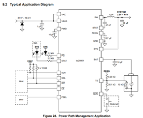
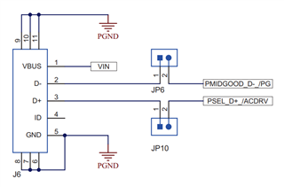
My customer consider use BQ25601D in their project, they get one question about the D+/D- connected between BQ25601, USB, and MCU. Could you help comment how should they connect the D+/D- line between those three items? Thanks.

Best Regards,

Will

  • Hi Will,

    The block diagram you have pictured above is from the BQ25611D which uses D+/D- input detection functionality. However, the part that you have referenced, the BQ25601 does not use D+/D-.

    Instead, the BQ25601 uses a PSEL pin with a HIGH and LOW option:

    More information can be found in the datasheet.

    Regards,

    James

  • Hi James,

    Thanks for your feedback. The corrected part # should be BQ25611D. For BQ25611D, how should I connect the D+/D- between MCU, charger and USB port? 

    Thanks and Best Regards,

    Will

  • Hi Will,

    The D+/D- pins of the BQ25611D should be connected to your USB D+/D- pins to facilitate the input detection algorithm described in Section 9.3.3.3.1 of the datasheet

    The BQ25611D does not have an explicit control scheme for a dual D+/D- system. Some of our other battery charger ICs, like the BQ25898D, have a digital output DSEL pin that can serve as a multiplexer control source for dual D+/D- connections. This thread may provide some additional information for you since it tackles a similar topic from another battery charger IC with both USB and MCU D+/D- connections.

    That being said, the D+/D- pins will perform input detection on whichever device is connected at the time of adapter plug-in. Usually, the USB adapter connection handles both the VBUS source voltage and the D+/D- signals. In our typical application example, the D+/D- pins are connected only to the USB adapter as shown in the figure from your original post. On our BQ25611D EVM, the USB adapter is connected via Micro-USB port (J6 shown below from the EVM User's Guide schematic). The USB connection handles both VBUS and D+/D-.

    Regards,

    James