Because of the Thanksgiving holiday in the U.S., TI E2E™ design support forum responses may be delayed from November 25 through December 2. Thank you for your patience.

This thread has been locked.

If you have a related question, please click the "Ask a related question" button in the top right corner. The newly created question will be automatically linked to this question.

TPS54240: Small switching frequency "audible" frequency in buck convertion 12V to 5V design

Part Number: TPS54240

Hello,

I am designing a power supply with a TPS54240QDGQRQ1 buck converter that  reduce from 12V to 5V and load from 500mA to 2A.

Unfortunatelly this is old design and I have to keep some part fixed until I have option to change. Those parts is the Output filer of buck converter that are 33uH and 44uF respectively

Even I tried to change the Rt (to find suitable frequency) and compensation network I cannot avoid very bad oscillation at switching node and switching frequency is quite low around 10Khz even I put Rt=205Kohm

Also this design has high input coil filter 100uH at it is undumped. I read i another thread that this could cause some problems and I would like to dump.

The thread is 

TPS54160A: Compensation Type 2 and beeping 

and it is talking about one document:

Input Filter Design for Switching Power Supplies (ti.com)

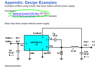
Whichi is explaing very well how to dump an LC filter and also has some zip with a MATHCAD files http://www.national.com/files/national_input_filter_design_for_switchers.zip

But I cannot access maybe because it is an old link. Do you have such a files, I would like to use for my calculsations

Thanks and best regards

Josep

  • Hello Josep,

    It is possible that your input is ossilating as a result of the undamped input filter.

    To damp it, pleas review section "PARALLEL DAMPED FILTER" in the appnote you linked.

    You can have a series R and C, determined by the two last equations in that section. 

    Additionally, it would be helpful if you could share waveforms and full schematic for review.

  • Hello Marshall,

    Thank you. Let's say calculations more or less I understand, what is difficult for is:

    * To calculate the power rating of the dumper resistor

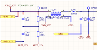
    * To fit this calculations to my real case that regarding the PI filter itself is strange because we have the following filter:

    We have additional in parallel to C202 and C203 (2xmore caps of 10uF at the input of two DC-DC, so total could be 10uF). The following cacluations if

    Cd=4C this means around very big capacitor 160uF if we count the 8 caps, 80uF if we count only the filter caps

    Rd=SQRT(L201/(C202//C203)) this means around 2.23ohms

    We have a resoance ripple of 4Vpp @12Vof DC input with a frequency of ~3,7Khz

    Just by "trying" I put Rd10ohms and Cd=10uF and the problem seems solve, but this is not matching with the criteria of the document description. But unless I would like to know the Pdiss in the Rd.

    By other side I would like to know that Mathcad files that are potentially shared in the document in all server from National ara available in new link. The link of the document is broken. And seems nice files for easy understanding

    Thanks for your help

    BR

    Josep

  • Hello Josep,

    These calculations would be for the ideal damping.

    It sounds like you were able to obtain "good enough" damping with your selected components in your latest evaluation.

    In terms of power rating on the damping resistance, I have found that 0603 and upwards would be OK for designs I work on.

    Personally, I haven't done any analytical calculations for it. It may not be exactly straightforward.

    It maybe best to validate through prototype experimentation.

  • I'll see if I can find a similiar filter designer, fyi.

    I know my colleague developed an excel tool.

  • Yes, please would be great

    thank you

  • Hello Jose,

    I attached a design calculator. Have a look.8308.InputFilterCalculator.xls