A related question is a question created from another question. When the related question is created, it will be automatically linked to the original question.
If you have a related question, please click the "Ask a related question" button in the top right corner. The newly created question will be automatically linked to this question.
[FAQ] BQ76952: Connecting battery cells to the BQ769x2 family of monitors
The BQ769x2 family of battery monitors has specific cell connection requirements. The following post provides answers to some common questions pertaining to cell connection:
Does the BQ769x2 support random cell connection?
The BQ769x2 devices do support a random connection sequence of cells. For example, cell-10 in a 16-cell stack might be first connected at the input terminals leading to pins VC10 and VC9, then cell-4 may next be connected at the input terminals leading to pins VC4 and VC3, and so on.
There are restrictions to random cell connection, though. Cells in a stack cannot be randomly connected to any VC pin on the device, such as cell-4 connected across VC9 and VC10 while cell-10 is connected across VC3 and VC 4, and so on. It is important that the cells in the stack be connected in ascending pin order, with the lowest cell (cell-1) connected between VC1 and VC0, the next higher voltage cell (cell-2) connected between VC2 and VC1, and so on.
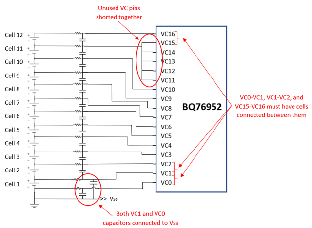
How do I connect unused VC pins if I have a reduced cell count?
For the BQ76952, VC pins 0, 1, 2, 15, and 16 should always be connected to actual cells, with cells connected between VC0 and VC1, VC1 and VC2, and VC15 and VC16 (or VC9 and VC10 for the BQ76942). All other cell inputs can be shorted to reduce the cell count. An example configuration can be seen in the image below, where a 12S battery pack requires 4 VC pins to be shorted together:
Additionally, after reducing the cell count, you must set theSettings:Configuration:Vcell moderegister to correctly reflect which cell inputs are connected; otherwise, CUV faults can trigger for the shorted cell inputs.
The following links provide more information on how to reduce the cell count and explain why certain VC pins need connections.
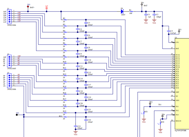
How should the input filter resistors and capacitors be connected?
The input filter resistors and capacitors are important for cell balancing, voltage measurement accuracy, and filtering of transients.
The following image provides a guide for connecting the cell input filter capacitors and resistors:
In this image, please note that both C22 and C23 connect from their respective VC pin to ground, rather than C22 being connected from VC1 to VC0. This is to prevent VC0 from being pulled below ground. Additionally, to ensure their effectiveness, all filter components should be placed as close as possible to the BQ769x2 device.