This thread has been locked.

If you have a related question, please click the "Ask a related question" button in the top right corner. The newly created question will be automatically linked to this question.

TPS92641: LED Voltag overshoot when PWM turns on

Part Number: TPS92641

Hi,

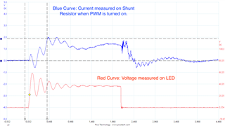
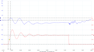
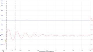
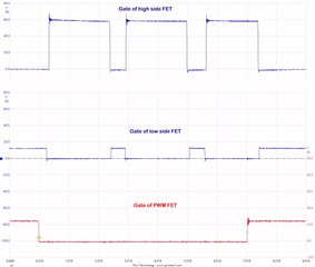
we have an issue with a TPS92641 design where the voltage on the LED significantly overshoots when the external PWM FET opens and turns on the light. Our schematic is pretty much standard. We chose quite a big inductor in order to keep ripple to a minimum, but using a smaller inductance doesn't improve the problem. We have tried several other changes, but without success so far.

So my question: What is causing the overshoot?

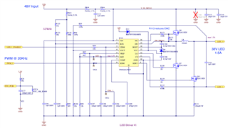
Here is the schematic:

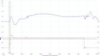
And this is what we see on the scope, when Q11 is turned off:

  • hello Thomas

    would you mind sharing the application here?

    for the overshoot, this might be due to fast loop response. can you try to increase C103 to 1uF and see if there is any improvement?

  • Hi Mason,

    our PCB is driving an LED which has ca. 38V forward voltage and is driven with 1.5A current. We did increase C103 for testing, but this creates higher switching losses and Q11 heats up significantly as with 20KHz PWM rate it needs to dissipate quite some heat then.

    Best regards,
    Thomas

  • hi Thomas

    what about the result of 0.1uF? 

    for one hand, it helps to decrease output ripple, for another, the switching frequency is around 334kHz, while the LC oscillation frequency is close to this value, increasing cap to 0.1uF can make the oscillation frequency away from switching frequency.

  • you can also try with 68uH inductor or change switching frequency to like 500kHz to skip 334kHz LC frequency.

  • Hi Mason,

    we have tried your proposed solutions. Here are our results:

    1. Smaller inductor doesn't change much - still same issue
    2. Increasing frequency to 500/600KHz doesn't change much - same as above
    3. Increasing size of C103 (we tried 100nF and 1uF) - reduces overshoot, but has side effects - see below

    The capacitor clearly reduces the overshoot, but apart from the heat issue it creates another side effect: It also increases the minimum on time that we need to use on the transistor to make the light turn on as the capacitor will need to be charged first. This basically means that we loose a good portion of the low-end dimming range which, but good low-end dimming resolution is actually what we wanted to achieve with the external shunt FET transistor in the first place. So this not a good solution for us.

    600KHz ringing:

    It appears that when the shunt FET turns off then first the voltage goes up due to the inductor trying to maintain the current. It takes a short time until the driver chip starts charging it again. So I would agree that this most likely somehow comes from the resonance of the inductance and/or capacitor. Still what I can't explain then is why changing the size of the inductor (we used 68uH instead of 220uH) shows almost no change here. Do you have any idea?

    Driver pulses on Chip Output (SW pin) vs. voltage:

    Best regards,
    Thomas

  • hello Thomas

    1. can you help check the resonance frequency before and after changing the inductor size/switching frequency?

    2. can you help add 20kHz PWM signal on Q11 and driver pluses on Q7 in your second waveform?

    3. what is the rising time of driver pluses on Q7? Have you tried increase R108?

  • Hi Mason,

    the resonance frequency is always 5 MHz (T = 200 ns).
    Rising time at Q7: 11 ns
    Changing R108 also to 100R both Gate resistors set to 1R makes no difference

    Changing the inductor from 220uH to 68uH doesn't alter the oscillation frequency - it is still 5MHz:

    Here is the measurement from the signal at the gates:

    Best regards,
    Thomas

  • Hi Mason,

    today we figured that putting a resistor in series with the output capacitor dampens the oscillation. Not sure though, if this is a good solution as it also will reduce the effectiveness of the output capacitor. Putting 50R in series with the 1nF capacitor looks like this:

    Best regards,
    Thomas

  • hello Thomas

    Sorry for the delay as I did not receive reply notice. 

    I would like to know if there is an additional LED board and there is something like cable connecting LED driver board with LED board.

    If yes, I guess the parasitic inductance of cable may contribute to the high overshoot since the oscillation frequency is quite high.   

  • Hi Mason,

    thanks for your answer. We checked this today and you are correct. The effect seen is indeed caused by the cable being too long. We have reduce it and it improved significantly.

    Best regards,
    Thomas