This thread has been locked.

If you have a related question, please click the "Ask a related question" button in the top right corner. The newly created question will be automatically linked to this question.

BQ25895M: BQ25895MRTWR charging issue

Part Number: BQ25895M

Hi, I designed a battery charging circuit using BQ25895MRTWR IC 

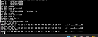
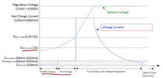
when the battery is drained completely (0V), and if we give the power, the ic is not charging the battery it is reaching a voltage level of 2.99V (3V) and stops, without reaching a specified voltage I can only set the values in the i2c  registers. 

Details of the battery is as follows.

capacity:5000mAH

battery voltage:3.7V-4.2V

link: https://www.innovoya.com/product-page/955465-5000mah-rechargeable-lithium-polymer-battery-cells-1

I am also attaching the schematics for your reference.

 BQ25895MRTWR review.pdf

  • Hi Delish,

    Can you provide a full register dump showing all register values when the battery is connected at 2.99V and charging is enabled?

    Can you also provide a scope capture that shows VBUS, IBUS (input current), VBAT, and IBAT (battery current).

    Please visit https://e2e.ti.com/support/power-management-group/power-management/f/power-management-forum/874557/faq-bq25890-faq-bq2589x-schematic-review-and-pcb-layout-design-tips for BQ2589X: Schematic Review and PCB Layout Design Tips.

    Please check https://e2e.ti.com/support/power-management-group/power-management/f/power-management-forum/790169/bq25895-4-layers-board-review---agnd-gnd-and-power-planes for detailed layout guidelines.

    Regards,

    James

  • I Am Not dumping any values to the registers in IC. It will be in the default state.

  • Hi Delish,

    The register dump is a read-out of all your register values so that I can see if there are any faults and check the conditions of the IC. The default register settings are only part of the information the device can report. If possible, please share all your register values when you see the charging issue so that I can try to replicate the behavior on my end.

    Draining the battery all the way down to 0V is usually bad for the battery cell, are you measuring the battery voltage at the VBAT pin of the IC or at the battery terminals?

    The scope capture that I mentioned above would help to visualize the issue you are seeing as well so I can compare to the waveforms I can gather on my end.

    Regards,

    James

  • Hi James,

    I want to explain my situation in detail.

    CASE 1

    Battery voltage: 2V

    The charger is connected, and the battery will charge till 2.99V after that battery voltage is not increasing. In that condition battery charging, IC won't give any output.

    Register values: Will be as default. (my assumption) Because the battery charging IC is not giving any output so I won't be able to dump or read register values.

    CASE 2

    Battery voltage:3.6V (Manually charge the battery using an external charger and connected)

    The charger is connected and the battery will charge. the device will turn ON.

    Register values

    i2c md 6A 0
    0000: 08 05 31 3e 20 13 82 8d 03 44 70 02 00 13 58 59 ..1> ....Dp...XY

    => i2c md 6A 0F
    000f: 59 50 00 00 08 3a ff ff ff ff ff ff ff ff ff ff YP...:..........

  • Hi Delish,

    Case 1) If the battery is charged to 2.99V, this would be enough to supply the device with power and access the registers. Also, if you have a valid adapter connected (5V according to your schematic) the adapter voltage should also keep the device turned on with the registers available. 

    There are read-only registers that report helpful information about device status and ADC values. The ADC conversion can be started by setting REG02[7] = 1b or by setting REG02[6] = 1b for continuous 1-second conversion. After conversion you can read the updated register ADC register values (See Section 8.4 of the datasheet for a list of registers). Of particular interest will be REG0E[6:0] which reports detected VBAT pin voltage, and REG12[6:0] which reports detected charge current through the BATFET. These are a couple of the registers I would like to check while your battery is stuck at 2.99V.

    Some measurements you should take to narrow down potential issues. Please measure these voltages as close to the IC as possible. Take these measurements when you see the device has stopped charging the battery at 2.99V:

    • VBUS voltage
    • PMID voltage
    • SYS voltage
    • BAT voltage
    • REGN voltage

    Can you confirm that I2C communication works when you connect the 2.99V battery only? Check REG09[5] to see if the BATFET is turned off.

    Also please provide a scope capture of the charging behavior. If this in not possible let me know.

    Case 2) These register readings look normal so the device is operating correctly when the battery is connected at 3.6V. In order to solve Case 1, I need the information described above.

  • Hi James,

    I was unable to get the register values initially so the reply got delayed sorry for that.

    Battery voltage: 2.505V
    Register values
    i2c md 6A 0
    0000: 48 05 31 3a 20 13 82 9d 03 44 93 02 00 13 00 00 H.1: ....D......
    => i2c md 6A 0F
    000f: 00 00 00 00 08 3a ff ff ff ff ff ff ff ff ff ff .....:..........
    VBUS voltage:0V
    PMID voltage:0.780V
    SYS voltage:0V
    BAT voltage:2.506V
    REGN voltage:0V

    I used an external tool to read the i2c registers of that IC.I hope that's the way you want.

    and I have an additional observation today,

    • I put my "battery 1" on charge for 2 days with an initial charge of 1.175V. & I observed that it has been charged to 1.838.

    based on my understanding battery charging IC it is not changing from trickle charge state to pre-charge.

    I have 2 questions also kindly answer the same.

    1. Will the IC, charge the battery in the default configuration?
    2. Is there any minimum required voltage for the battery which is connecting to this IC?

  • Hi Delish,

    1) The IC will charge the battery with the default settings. The trickle charge current should be 100mA for a battery below 2V (typically). Can you check the charging current (IBAT) when the battery is connected at 1.8V similar to your last experiment?

    2) There is no listed minimum battery voltage for charging to begin. The charger should apply trickle charge to the battery unless there is some protection circuitry blocking the charge path.

    For I2C to be active and for the battery to supply the system (SYS node) you would need at least 2.3V at the BAT pins. This is when the battery is used as the source. During charging the source should come from VBUS which operates from 3.9V to 14V.

    In these cases where the device is not transitioning to the next charging stage, we need to see how the battery current (IBAT) is behaving as well as the voltage levels throughout the power path in forward mode charging (VBUS -> PMID -> SW -> VSYS -> VBAT). It is difficult to asses the issue without a clear picture of the power path current behavior.

    Regards,

    James

  • Hi James I checked the charging current when we connect the 1.3V battery, which is 4.6mA. after reaching 1.8V it is 8μA. 

  • For Battery with 3.53V charging current is 1.4A

    For Battery with 2.1V charging current is 11μA. 

  • Hi, James

    From my understanding. The following table data is required, right? kindly confirm.

      t=00:00:00 t+01:00:00 t+02:00:00 t+03:00:00 t+04:00:00 t+05:00:00
    VBUS            
    PMID            
    SW            
    VSYS            
    VBAT            
    charging current (IBAT)            
  • Hi,

    Because of the holidays, we will get back to you after Jan. 3, 2023.

    Thank you for your patience,

    Ning

  • Hi Ning,

    Sure. In the meantime I will collect the data you required and share the same.

  • Hi Delish,

    A table like the one you suggested in your last reply would be helpful.

    Can you also provide a scope capture that shows VBUS, IBUS (input current), VBAT, and IBAT (battery current)?

    When you have your input adapter connected to VBUS and the battery voltage is 1.3V with charging enabled, what is the value of...

    • REG0E[6:0]
    • REG0F[6:0]
    • REG10[6:0]
    • REG11[6:0]
    • REG12[6:0]

    Make sure to run an ADC conversion once the conditions are set to get the most recent ADC readings.

    Regards,

    James