This thread has been locked.

If you have a related question, please click the "Ask a related question" button in the top right corner. The newly created question will be automatically linked to this question.

TPS548A20: Output Cap range

Part Number: TPS548A20
Question 1:  Output Capacitance Range:
The datasheet indicates that we should try to set the 2-pole L-C filter at a frequency at or below the internal zero frequency (between 6 and 12kHz).  This approach results in an unrealistically high value of required output capacitance. 
Using the example in the datasheet, a 12V to 0.6V converter is switching at 600kHz.  The inductor value is 0.36uH. Table 1 shows that the fzero is located at 6kHz.  In order to set the 2-pole frequency value to be at 6khz, we would need almost 2000uF of capacitance.  This is obviously unrealistic.  Table 2 indicates that the circuit can operate with 300uF capacitance.
Can you clarify how to determine the min and max allowable output capacitance, and how to determine the zero-dB crossing and approx phase margin?  Are there any design guides or spreadsheets for the TPS548A20?
Question 2:  Vo connection with remote sense
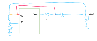
The load for our design is located several inches from the TPS548620.  Please refer to the attachment.  In order to minimize the DC load regulation error, the feedback will be derived from a sense line connected at the load.  My question here is whether we connect the Vo pin to the remote sense line (yellow line), or do we feed a voltage at the output of the inductor to connect Vo (red line)?  
Thanks...Guy
  • Hey Guy,

    Question 1: The min and max allowable capacitance for your system would need to be determined using a small signal measurement conducted on the EVM. 

    For minimum output capacitance the loop crossover frequency must be less than one-half of the switching frequency (300 kHz), and the phase margin at the loop crossover must be greater than 50 degrees.

    For maximum output capacitance, adopt an extremely high output capacitance and lower or raise depending on if the phase margin loop crossover is greater than 50 degrees. (> 50 degrees means the system will be stable.)

    I would say to design your system based on your ripple and transient requirements then adjust for stability.

    See section 7.3.3 of the datasheet for more information.

    Question 2: You won't need to feed a voltage at the output of the inductor using a separate trace (red line) Just connect the VO, and FB node to the point that you would like to regulate at. If you are regulating at the load, then all you will need is the blue trace and the yellow trace seen in your diagram. 

    Thanks,
    Caleb

  • Hi Caleb,

    Thanks for getting back to me so quickly.

    I understand that the minimum requirements need to meet the crossover/phase margin requirements.  How do I calculate the crossover frequency and phase margin?  I have tried using the WEBBENCH, but it does not run frequency domain analysis.  Thanks.

  • Hey Guy,

    I'll be closing this thread since we're communicating through email now.

    Thanks,
    Caleb