


Hi ,
I want to use this device to open P-Channel Fets on the high side during a failure. So I assume that I would use the active low version of the device to drive N channel Fets that would be normally on and these would pull down the gate of the P channel Fets, turning them on in the normal state. During OV, the output would go active low, turn off the N channel and thereby turn off the P Channel. however, I am having a reasonably hard time understanding the data sheet. The data sheet has a specification for source and sink for an open drain output which doesn't make sense to me.
Can you simplify the output specifications?
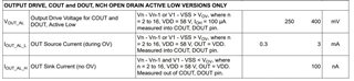
Specifically - this specification on page 7 of the user data sheet for part number BQ77216
VOUT_AL Output Drive Voltage for COUT and DOUT, Active Low Vn - Vn-1 or V1 - VSS > VOV, where n = 2 to 16, VDD = 58 V, IOH = 100 µA measured into COUT, DOUT pin. 250 400 mV
IOUT_AL_L OUT Source Current (during OV) Vn - Vn-1 or V1 - VSS > VOV, where n = 2 to 16, VDD = 58 V, OUT = VDD. Measured into COUT, DOUT pin. 0.3 3 mA
IOUT_AL_H OUT Sink Current (no OV) Vn - Vn-1 and V1 - VSS < VOV, where n = 2 to 16, VDD = 58 V, OUT = VDD. Measured out of COUT, DOUT pin. 100 nA
Is (Vn - Vn-1 or V1 - VSS > VOV) just saying that any cell that exceeds V max causes the output to become active and I don't understand why there is an output current from an open drain drive.
Thanks for any help in advance.
Richard

