Hi Experts,
My customer faced an EMC noise issue on LM3409-Q1.
Could you please give me any advice?
Issue.1
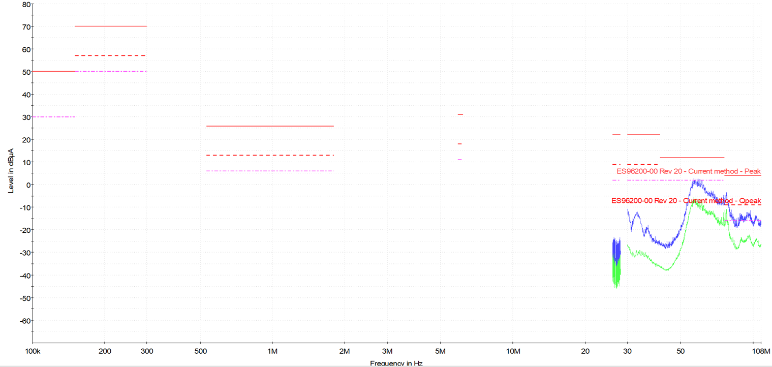
They are conducting an EMC test (CE) on the DMD headlamp, but the noise in the high frequency band (50MHz~100MHz) is out of specification.
The noise seems to be coming from the LED output line, as it goes down when the LED drive cable of the DMD is removed.
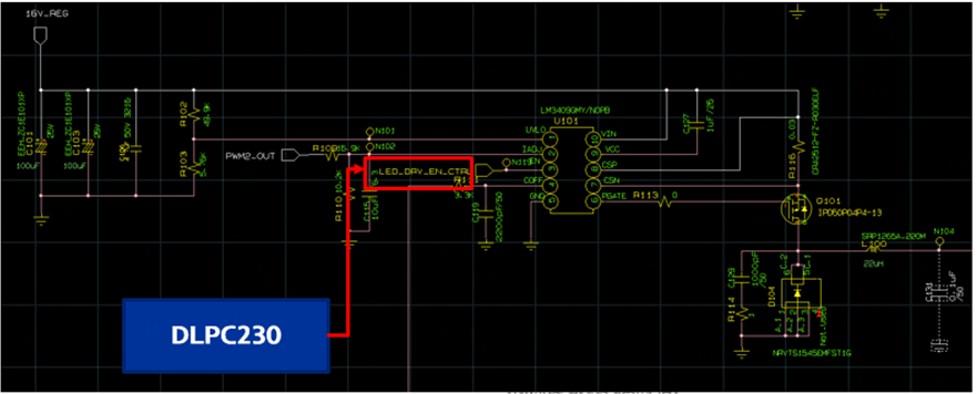
The LED driver is using the LM3409-Q1 in the Recommend circuit, but this product does not seem to have a spread spectrum function.
They would like to ask if there is any way to improve EMC.
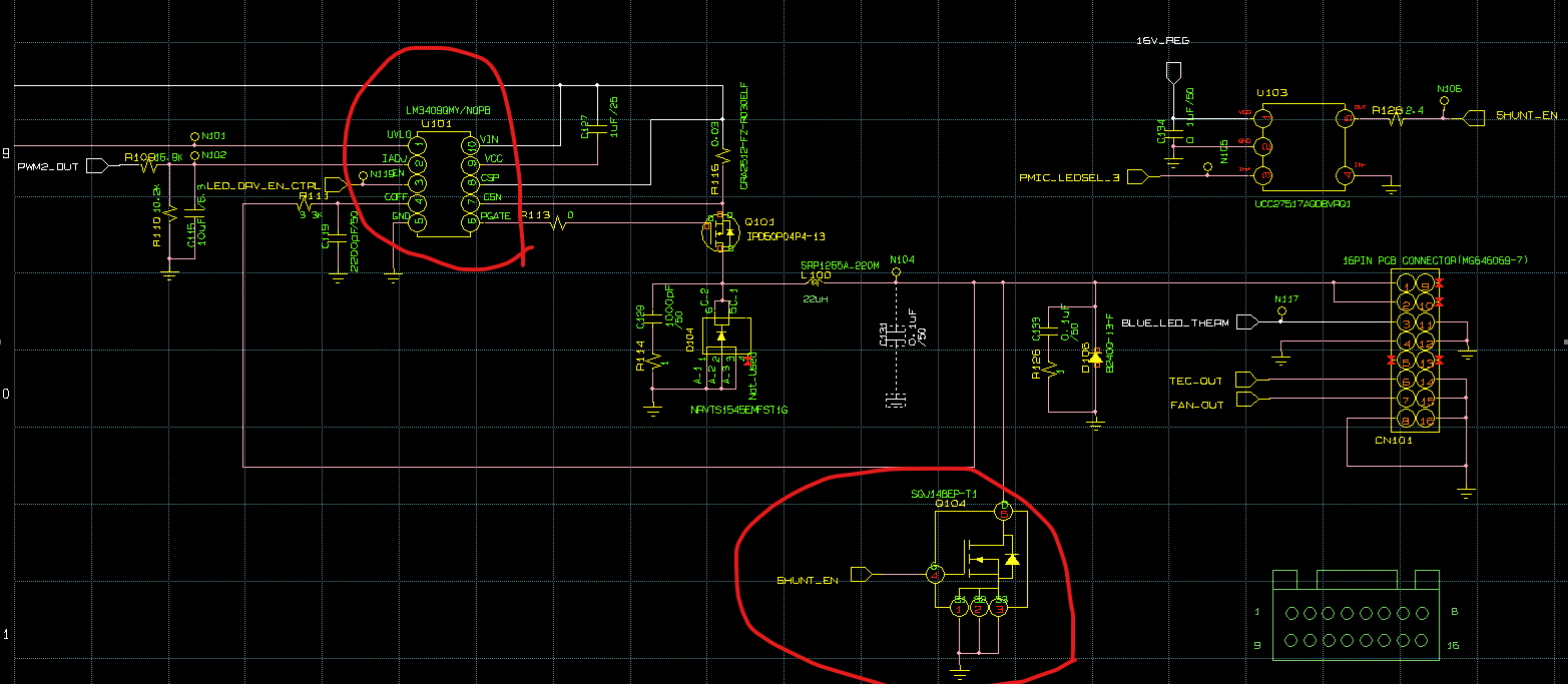
In addition, in the case of DMD, shunt FET (Q104) is also controlled, and this effect seems to be large.
I wonder if there are applicable idea regarding shunt FET control in DLPC230 to improve EMC.
Issue.2
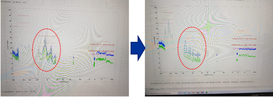
This time, Voltage CE is out of spec (500KHz~1MHz).

DLPC230 is controlling on/off of LM3409 in DMD reset and cmpliment bit, and if this pin is disconnected from being controlled, it has been confirmed that the corresponding band noise is reduced as shown below.

When controlling the on/off of the LM3409, measures to reduce EMC noise are required, so they request a review.