Hello.
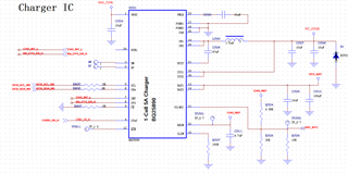
I am using the BQ25890 for the tablet charging management.
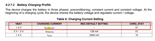
I found a issue, when the tablet placed a long and long time, the voltage of the battery would low down and go into the over-discharge protection @2.8V, and then the output of the battery module is 0V.
But in the datasheet , the BQ25890 would consider that the battery is in the short state and give up to charging the battery module.
any way to fix it?
tks.