This thread has been locked.

If you have a related question, please click the "Ask a related question" button in the top right corner. The newly created question will be automatically linked to this question.

UCC28740: Some questions about the datasheet and design of UCC28740

Part Number: UCC28740
Other Parts Discussed in Thread: UCC28704

Hi,

    I have been learning UCC28740 and I have some questions of the datasheet.

   1. Why does Control loop enter CC-regulation mode when TDM/TSW reaches a 42.5% limit? How does 42.5% come from?

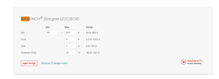
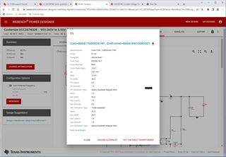
   2. Now I would like to design a flyback topology and the Vin=390V DC, Vout=48V and Iout=5A. Also, two mosfets are adopted here to improve the efficiency of this topology. Could you pls provide some guidance to me about the design of transformers and this topology?

   Thank you! 

  • Hello,

    I am looking into your inquiry and will get back to you shortly.

    Regards,

  • Hello,

    1.)

    The UCC28740 was designed to operate with a maximum Dmag duty cycle of 42.5% when the controller is operating in constant current mode.

    2.)

    The transformer turns ratio is selected based on this maximum Dmag, minimum input voltage and maximum duty cycle.  Calculations for the transformer turns ratio and transformer primary magnetizing inductance are in the data sheet. 

    Also there is a WEBENCH design tool that can help with the design process that can be found at the following  link.  Just search on Webench.

    https://www.ti.com/product/UCC28740?keyMatch=UCC28740&tisearch=search-everything&usecase=GPN

    Enter your input and output power requirements.

    Open the design and click on the transformer on the schematic.  It will give design guidelines for the transformer based on the input and output power requirements that you entered.

    Regards,

  • Hi Mike,

        Thanks for your answer! There are still some questions.

         1. Is this figure 42.5% derived by experiment rather than calculated?

         2. How can we do to avoid TDM/TSW reaching 42.5% limit when designing this flyback topology?

         3. In Webench, we could only input Vin a AC value, but I want to input Vin=390V DC. Also, I'd like to have two mosfets in this topology but the design is only for one mosfet.

       Thank you!

  • Hello,

    I am reviewing your inquiry and will get back to you shortly.

    Regards,

  • Hello,

    Please see my responses below.

         1. Is this figure 42.5% derived by experiment rather than calculated?

    a.) The UCC28740 was designed to operate with a maximum Dmag duty cycle of 42.5% when the controller is operating in constant current mode.

    b.) To ensure the controller operates correctly you need to select the transformer turns ratio at the minimum inputs voltage at Dmax and Dmag max of 42.5%

         2. How can we do to avoid TDM/TSW reaching 42.5% limit when designing this flyback topology?

    a.) Avoid contestant current trip point at max load.

    b.) You could design for 110% load and if your load never hits it you will not enter constant current.

         3. In Webench, we could only input Vin a AC value, but I want to input Vin=390V DC. Also, I'd like to have two mosfets in this topology but the design is 

    a.) Just enter 390V/2^0.5 for the maximum AC voltage.

    b.) For the minimum voltage just enter 390V/(3*2^0.5)

    Regards,

  • Hello,

    Just checking in.  Did this resolve your question? 

    If this did answer/resolve your question could you please select resolved?

    Regards and Thanks,

  • Hi Mike,

        I am sorry that I could not figure out how to avoid constant current trip point at max load and what constant current trip point at max load is. Also, how to design with two mosfets flyback.

  • Hello,

    I am reviewing your inquiry and will get back to you shortly.

    Regards,

  • Hello Skylar,

    The UCC28704 will always be in constant current control it the load is higher than the IOC trip point.  If the load is less than than the IOC trip point the device will operate in constant voltage mode.

    What I have recommend earlier was for you to design your converter for 110% more current than you need.  If you do this and load does not reach a 110% the controller will not operate in CC mode.  However, this is not disabling CC mode, also CC mode cannot be disabled with this device.

    Regards,