This thread has been locked.

If you have a related question, please click the "Ask a related question" button in the top right corner. The newly created question will be automatically linked to this question.

BQ25890: Questions of BQ25890

Part Number: BQ25890

Dear Team,

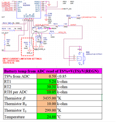
At present, according to the table provided by TI's official website, the RT1/RT2/RTH resistance value should be calculated, combined with the actual output value of VREGN, it is found that the read temperature will fall at about 45 degrees Celsius, which is consistent with the actual temperature and table calculation (25 degrees) there is a gap, so in the part of the base value (ring temperature), which parts need to be adjusted?

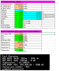
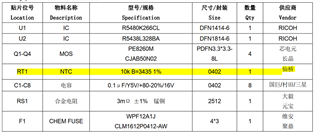
In addition, the NTC specifications inside the battery are attached as follows:

Many Thanks,

Jimmy

  • Hi Jimmy,

    You could find that the value of VREGN does not change the final results. The percentage of the the TS voltage over the VREGN matters. What is the unit of the 45 in your capture Temperature = 45.53..? If the value is 45% and you can put it the cell C93, you should get 45C. 

    Regards,

    Eric 

  • Hi Eric,

    In my case:

    - I set the TS division resister are 5.23k / 30.1k

    - REGN voltage =5V

    Use the NTC thermistor inside the battery (10k ohm), but the charger temperature still is a constant, so do you  have any suggestions to me? It won't change with the external temperature.

    Many Thanks,

    Jimmy

  • Hi Jimmy,

    We'll get back to you with an update.

    Regards,

    James

  • Hi Jimmy,

    I want to make sure I understand the issue you are facing here.

    The TS pin does not deal with IC temperature. The TS pin works with the resistor divider network and the NTC thermistor to monitor the battery temperature. From your last response where you mention "charger temperature" it sounds like you are talking about the IC temperature, which is monitored using TJ (junction temperature). Let me know if I am misunderstanding you.

    The TS pin voltage is monitored as a percentage of VREGN. This percentage changes as the NTC thermistor reacts to the battery temperature. The boundaries of the JEITA temperature range are related to the TS pin voltage (as percentage of VREGN) and are listed in Section 8.5 of the datasheet under the heading JEITA THERMISTOR COMPARATOR (BUCK MODE). There you will find the percentage values that correspond to T1 through T5. From there, the value of VT1 through VT5 can be calculated by multiplying VREGN by the corresponding percentage. (ex. VT1 = VREGN x 73.25% = 5V x 0.7325)

    RTH_COLD and RTH_HOT can be chosen based on the required temperature range for your application. The NTC thermistor datasheet should have a list of resistance values for different temperatures. You can use these values to determine your COLD and HOT JEITA thresholds. The RTH_T1 and RTH_T5 values from the datasheet were chosen assuming a temperature range of 0°C to 60°C.

    Note that RTH_COLD = RTH_T1 and RTH_HOT = RTH_T5.

    Regards,

    James