This thread has been locked.

If you have a related question, please click the "Ask a related question" button in the top right corner. The newly created question will be automatically linked to this question.

TPS650861: Setting OTP but not work

Part Number: TPS650861
Other Parts Discussed in Thread: TPS650860EVM-116, , IPG-UI,

Hi,

I am working on the TPS65086100 OTP setting, but we don't burn. below is my step:

1. We pull up 7V in CTL4.

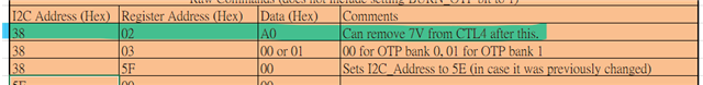
2. Sending OTP setting all register( Address:0x38 ) command by I2C.(OTP register create by OTP generator)

3. We pull down 7V in CTL4.
4. Still power-on Vsys 12V

5. Sending setting register( Address:0x5E ) command by I2C.

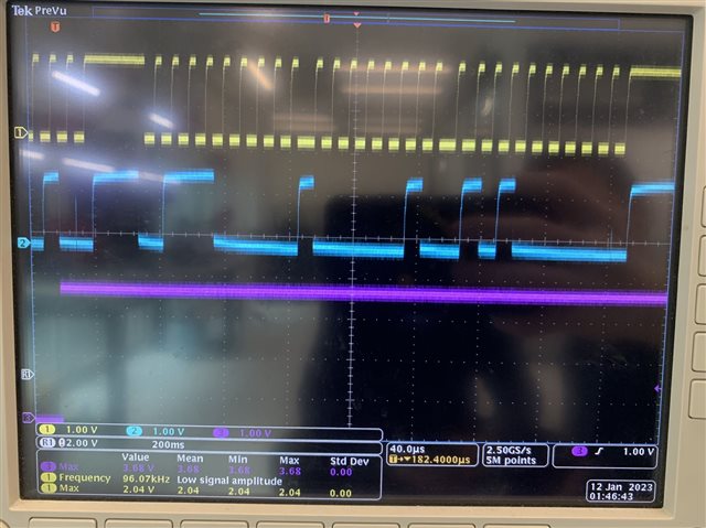
We can read register of 0x38, but read register of 0x5E is all zero. And all CTL pin pull-high didn't open any buck. Did I do any step wrong?

  • Hello, 

    Thank you for reaching out via E2E. 

    First, what are you using to program the TPS65086100? Are you using either the BOOSTXL-TPS650861 or TPS650860EVM-116 and the IPG-UI tool?

    We can read register of 0x38, but read register of 0x5E is all zero.

    Can you please double check and verify the registers that read all zero are at address 0x5E and not actually 0x38?

    When not in programming mode (i.e. no 7V pull up at CTL4) registers at address 0x38 are expected to read all 0. As long as you are correctly powering the TPS65086100 via Vsys 0x5E registers should never be all zero. 

    Regards,

    Garrett

  • Hi,

    Appreciate for help.The TPs65086100 is soldering on our PCBA,and I am using the STM32 sending command by I2C. I will double check about register of 0x5E.

  • Hi, 

    Below is my OTP_CTL1 bit settins command, and purple rail is 7V pull-up timing. After setting should acess in program mode, but send other register of 0x38 didn't get ACK. So i suspect it is not acess program mode.

  • Hello, 

    Thank you for the response and waveform capture. Does this mean you have confirmed you are actually unable to access the registers at address 0x38? Are you able to read values from the registers at address 0x5E? You do not need to be in programming mode to read/write to registers at address 0x5E. 

    Also, the waveform you provided shows the pullup is only 3.68V, not 7V. You will need to raise the pullup supply to 7V to access programming mode. 

    Regards,

    Garrett 

  • Hi, 

    Yes, we can acess 0x5E, but can't acess 0x38 after write OTP_CTL1 bit and pull down 7V.(Purple rail in scope is control signal for 7V of switch)

    I have a little experiment, only active LDOA3 by setting register of 0x5E in 4 register without setting 0x38, check below.

    addr > data

    29 > 0x0D,

    42 > 0x01

    9B > 0xAA

    A1 > 0x01

    But LDOA3 didn't output, is that normal? Should we only active TPS65086100 after setting register of 0x38?

  • Hello, 

    Let me first address your questions relating to your attempt to turn on LDOA3 output. I replicated your experiment with a TPS650861 device and LDOA3 correctly output 1.2V.  This leads me to believe there may be an issue with the I2C communication on your board. To help debug this can you provide me a register read of all registers at address 0x5E after you attempt to enable LDOA3. 

    Should we only active TPS65086100 after setting register of 0x38?

    Please refer to the FAQ linked below for an answer on this. In short there is no issue performing the experiment you did, but the registers at address 0x38 need to be programmed according to the OTP generator tool for all parts of the TPS650861 to work as described in the datasheet.

     https://e2e.ti.com/support/power-management-group/power-management/f/power-management-forum/1179009/faq-tps650861-evaluating-the-user-programmable-tps650861?tisearch=e2e-sitesearch&keymatch=pmic# 

    An issue with your I2C communication would also explain why you are having trouble accessing the registers at address 0x38. Before you remove the 7V at CTL4 please check if you can read the current value of OTP_CTRL1. 

    Best Regards,

    Garrett