This thread has been locked.

If you have a related question, please click the "Ask a related question" button in the top right corner. The newly created question will be automatically linked to this question.

LM5109B: Half bridge converter with strange high peaks

Part Number: LM5109B
Other Parts Discussed in Thread: LM5109

Dear Support,

I would need some help in a LM5109BMA Half-Bridge Converter design.

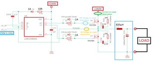
The LM5109 mounting: 2x PWM signals control the LM5109BMA inputs which drives 2x Power MOSFET (Idmax = 56A) and then the switching output voltage HS is filtered by an inductor and big capacitor to create a linear output voltage HS(LC) so I can adjust by software the HS(LC) voltage from 0 to 24VDC. LM5109BMA is supplied with 12VDC and the MOSFETs by 24VDC / 200W power supply:

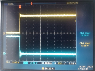
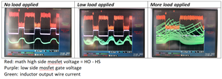
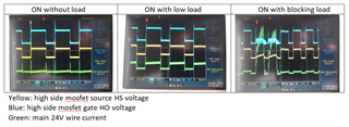
The application: I connect a load between HS(LC) voltage (adjusted to 16VDC for example) and ground and I increase smoothly the current consumption with a low load (see middle scope). The HO LO HS signals are stable and the 200W power supply current consumption is increasing to around 4A. 

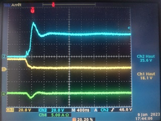
I increase the load again smoothly and suddenly the current is very high and signals unstable and the switching current presents 2 20µs peaks of 60A! This is too high from the 200W PSU. In normal condition the load is not consuming more than 8A when I connect directly the 24VDC PSU on it.

After the load is removed or reduced, the signals and converter are again stable and working fine:

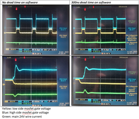
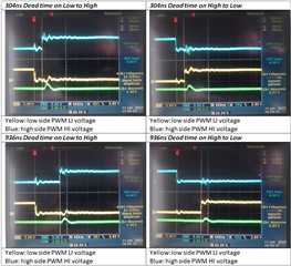
Do you have any idea of the reason of these 60A high current peaks? And how to correct? 

Thank you in advance for your feedbacks.

Best Regards,

Julien

  • Hi Julien,

    Thanks for your interest in the part. It looks like you may have shoot through in the half-bridge. How much dead time are your using? You may need to increase the dead time on the part.

    For your low load oscilloscope image, what type of resistance do you have? What type of load does your buck converter stop working?

    Can you take an oscilloscope image that shows both low side gate voltage, the high side gate voltage, and the 24V wire current?

    Best Regards,
    Ethan Galloway

  • Hello Ethan,

    Many thanks for your fast answer. Because it is generated by direct fast PWM 31KHz from AtMega328p without prescaling, the dead time is not really managed. Of course I can recreate my own PWM signals and integrating the dead time by using the timers but the PWM frequency will be lower.

    As you can see on this 400ns/div image, in normal free load condition the low and high side HI (yellow) LI (blue) voltages are very synchronous:

    So the low and high side HO (blue) LO (yellow) gate voltages are also without ON/ON time:

    Green signal is the 24V high drain wire current.

    Regarding the load type, we use the converted voltage to power a 3-phase bridges mosfets motor driver and then the load applied on the motor makes the converter load vary until the motor stalls (and the 62A current peak appears) at maximal motor load. We when release the load on the motor, the converter presents again good signal conditions.

    EDIT :

    I changed my software to include 300ns dead time:

    It works fine if I apply a low load but the signals are noisy and disturbed when applying an high load and then the high side mosfet burnt. Perhaps it is a sign that the dead time has to be increased?

    Best Regards,

    Julien

  • Hi Julien,

    Thanks for the results and your dead time measurements. You probably don't need 900 ns of dead time. I think 300 ns of dead time should be good enough for now. You can tweak the dead time lower later.

    Can you measure HO with respect to HS and put this on the same plot with LO? To get the HO-HS measurement, you can use a probe on HO and a probe on HS and then subtract the difference.

    Also, can you measure the inductor current?

    Best Regards,
    Ethan Galloway

  • Hello Ethan,

    Here is the requested picture for 300ns dead time:

    The converter is quickly in failure and I cannot apply so much load.

    Thank you for your support. If you have any code example or library including dead time I am of course interested.

    Best Regards,

    Julien

  • Hi Julien,

    That inductor current doesn't look to good. The inductor current is usually a saw tooth waveform. How are you measuring these signals? Make sure to use the tip and barrel method to get the best signals.

    By the way, how did you get 820 uH for your inductor value? That seems too high. I calculated a minimum inductance of only 53 uH for a 200 W power supply that outputs 12 V.

    What's the current saturation rating for the inductor?

    Best Regards,
    Ethan Galloway