This thread has been locked.

If you have a related question, please click the "Ask a related question" button in the top right corner. The newly created question will be automatically linked to this question.

LP87524P-Q1: Question about HW desgin

Part Number: LP87524P-Q1

Hi,

My customer is designing own board with LP87524P and their design has some differences with LP87524EVM. Would you pls help to check and give your comment?

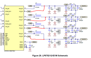
1.  In LP87524EVM, the input voltage feed section of PMIC uses 4 filtered supplies. Customer only uses 2. One is connected to VIN_B0/B1 and another is connected to VIN_B2/B3. 

2.  In LP87524EVM, FB is connected after the caps. Customer designs the FB is connected before the caps as below red lines. 

Thanks,

Chris

  • Hi Chris,

    1. This is really up to customer to decide if they want to use different filtering scheme. Just need to make sure filters can handle needed input current for two BUCK.

    2. The intention with connecting FB close to point-of-load (POL) is that this way IR drop between local and POL can be minimized. And by showing clearly that in schematics and should be used in layout as well similar way.

    Br, Jari