This thread has been locked.

If you have a related question, please click the "Ask a related question" button in the top right corner. The newly created question will be automatically linked to this question.

CSD87381P: Assembly related problems

Part Number: CSD87381P

We have run into problems during PCBA.

The symptoms seem to indicate a cold solder joint with an oxide layer between the solder on the PCB pad and FET metal pad.

Below is an example of a removed part from assembled board with the gate pad dull and the cause of open after assembly:

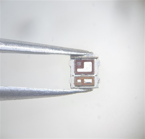
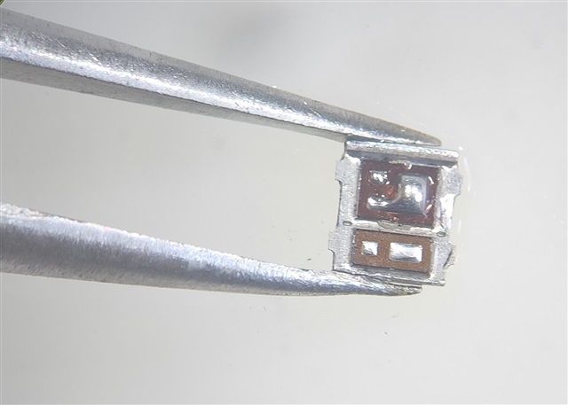
The dull pad can be soldered, so there does not seem anything wrong with the actual pad:

These parts come pre-tinned. What would cause the metal pad on the part to become oxidized and form an open during assembly?

  • Hello Lauri,

    Thanks for your interest in TI FETs. The pads on the CSD87381P are plated with Ni-Pd-Au and should not be oxidized. Have you followed the TI recommended PCB land pattern in the datasheet? Can you please share the details on the stencil openings, stencil thickness, solder paste and reflow profile. How is the part been released when placed onto the PCB pads - is it by pressure or by actual thickness of the device? I suspect the pads on the larger die are not making contact with the solder paste during placement. I have shared this post with our SMT expert to get his input on your issue. He may have better insight into what is causing the issue. The link below is to an application note for TI chip scale devices which are very similar to the power block II which uses LGA die on a copper clip. It provides some areas to look at when there are assembly issues. I'll update you as soon as I hear back from our SMT expert.

    https://www.ti.com/lit/an/slvafh0/slvafh0.pdf

    Best Regards,

    John Wallace

    TI FET Applications

  • Hi Lauri,

    Since we have moved this issue to regular email and have a call scheduled for later today, I am going to close this thread.

    Thanks,

    John