This thread has been locked.

If you have a related question, please click the "Ask a related question" button in the top right corner. The newly created question will be automatically linked to this question.

TPS65735: There is a problem with TPS65735 detection

Part Number: TPS65735

The BTL output end of LCRP--LCRN of PCB TPS65735 is connected to oscilloscope for test. The waveform tested under no-load condition (or connected to 1M resistance load) is as follows. The timing signal of this waveform is normal;LCRP-- The BTL output of LCRN is connected to the LCD load, and the waveform timing signal is abnormal; What's going on here
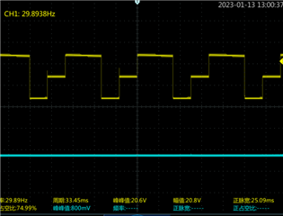
Click here to play this video

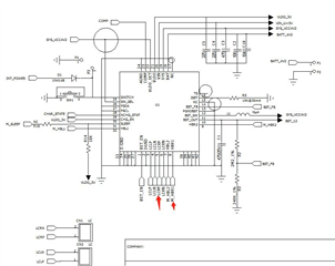
  • This is our circuit picture, please check

  • Hi,

    Device expert is based in US timezone and they have public holiday today. Please expect response by tomorrow.

    Br, Jari

  • Hello, 

    Thank you for reaching out via E2E. The TPS65735 is a legacy device with limited resources available. Please expect some delay in response as our team works on your request. You can expect an update later this week. Thank you for your patience. 

    Best Regards,

    Garrett 

  • Howdy.

    From looking at section 5.3.5.1 of the datasheet, it looks like your LCRP output is sometimes changing from the Charge+ to Charge- state as expected, but then it stays in the charge+ state for too long as shown in the video.

    I have compared your circuit to the TPS65735 Evaluation board and found no significant errors.

    Can you probe HBR1 and LCRP?

    Best,

    - David Martinez

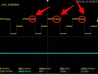
  •  When the H-Bridge terminal is in NO loading mode (or connected to a 1M resistance load), the waveform timing is normal. However, there is a slight difference in the pulse falling edge, as shown by the red arrow in the TESE1 picture. (Yellow pulse is HBR1, blue pulse is LCRP)
    When the H-Bridge terminal is connected to the LCD load, the timing error occurs.
    The BUG is that the H-Bridge terminal works properly when it is in the chanrge+ state, but it does not work properly when it is switched to the OPEN state.

  • Howdy.

    1) With the LCD load, LCRP begins to slowly ramp down when HBR1 goes low. This means that it is discharging through a resistive element in the OPEN state or to ground in the GROUNDED state. This is likely the cause of why LCRP is staying high longer than expected.

    2) Make sure you are not overloading the boost converter output.

    3) Is there a reason why you are using the GROUNDED and OPEN states? The EVM user guide shows data for only alternating between the CHARGE- and CHARGE+ states. I think a good step for debugging would be to use only the CHARGE- and CHARGE+ states to see if you are still seeing this abnormal waveform.

    Best,

    - David Martinez

  • According to the specification of TPS65735, the OPEN state and GROUNDED state can make the H-Bridge terminal output 0 level and the LCD join at 0 voltage. This is in line with the functional design requirements of 3D glasses products.
    According to the TPS65735 specification, the H-Bridge terminal has four states available for product design applications: OPEN/charge+/charge-/GROUNDED.
    By observing the oscilloscope test data of H-Bridge terminals, it is found that the charge+/charge-/GROUNDED state is normal.
    Only the OPEN state is abnormal. This test data can also prove that the boost conversion with load performance is normal.
    The abnormal condition tested by the OPEN state does not conform to the function description of the TPS65735 specification. How to solve this BUG?
    Please test the LCD loading on your TPS65735 EVM PCB. Will the same phenomenon be found in the OPEN state of H-Bridge terminal?

  • Howdy.

    Unfortunately, we do not have a tps65735 EVM in our lab so we cannot test this.

    The OPEN state does not make the H-Bridge output 0 level. All 4 switches are open in this state, so both terminals of the LCD, a capacitive load, are left floating and thus the capacitor cannot charge or discharge. Essentially, there is no charging state across the lens so it remains in the same level as its previous state. In your case, it will stay high because it has transitioned from CHARGE+ to OPEN. I don't believe this is a bug. This solution provides the expected behavior with a 1M Ohm load because there is nothing in the load to store charge during the OPEN state.

    To correct this issue, I suggest using GROUNDED instead of the OPEN state for the LCD load.

    Best,

    - David Martinez