Other Parts Discussed in Thread: LM5113
My question is on the
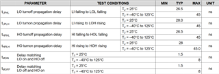
Lm5113 part , the Tmon and Tmoff shows a delay matching of 1.5ns typical max 8ns I have a few questions
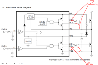
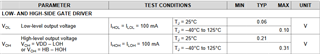
- What is the output impedance of the driver during that “dead” time
- How was the 8ns max determined?
- Is that a tested parameter?
- What is the distribution of that delay?