This thread has been locked.

If you have a related question, please click the "Ask a related question" button in the top right corner. The newly created question will be automatically linked to this question.

TPS4811-Q1: Controlled Overcurrent Potection threshold

Part Number: TPS4811-Q1

Hi,

I am looking to potentially use the TPS4811-Q1 for a high side driver however one of the requirements is to have firmware adjustable current limit for each channel

Initially looking at this part I was hoping to use the built in functionality without using external current sense and parts. I attempted to do this by replacing RIWRN with a voltage controlled resistor however I need more information on the current sensing and over-current protection circuit.

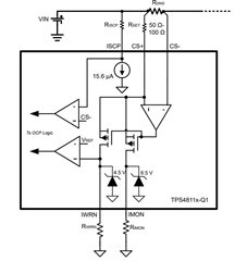
What is the Vref that IWRN pin voltage gets compared to? and What is the maximum and minimum current output on IWRN and IMON?

Secondly do you have another suggestion how to make this over current protection level adjustable? Without the need for a complete external circuit.

  • Hi Vlad,

    Welcome to E2E!

    Vref = 1V

    Current through IWRN resistor = Vref/RIWRN

    Current through IMON resistor = Load current  * Rsns / Rset *0.9

    Can you help with more details on the end product and use case ? Why do you want to adjustable current limit  ? Is it needed during startup or on-the-fly during system in operation ?

    Best Regards

    Rakesh

  • The adjustable current limit is to protect different loads at different points in order to avoid damaging the loads. I.E a motor might need a limit of 10A but a digital circuit might need a limit of only 1A

    I need to do something similar with the timing capacitor.

    Secondly do you have a suggestion on paralleling the two channels? I ideally in order to keep PCB traces and components to lower value I would design let's say 5 channels at 30A but then could double that by paralleling. I am worried however that if there is an imbalanced opening time the short circuit or OVC protection kick in and then could create an oscilation between the two channels

  • Hi Vlad,

    Thanks for the information. What is the end product? is it for automotive application ?

    If I understand correctly, you want to parallel one out of 5 channels at 30A on one board with another one channel on another board. What is the motive ? Why cannot we design each channel at higher current ?

    Yes, as you rightly pointed out. There is a risk of imbalance current sharing between channels and one may trigger the fault early than the other.. but eventually both channels will get turned off.

    Best Regards

    Rakesh

  • Hi,

    The application is a smart power management system for industrial application.

    The board already is quite size contained so design from 30A would allow thinner tracks and less heat sinking on each of the fets/pre-charge. This could be tricky to fit in the current dimensions if everything is 60A. The reality is most 98% of the loads will be <30A however to design the whole board for the 2% is both more costly, difficult and inefficient.

    What i am worried on is an oscillating turn-off pattern between the two units so effectively there needs to be a delay sharing circuit to allow enough time for the two mosfets to balance out by the self heating efect.

    I was curios if you had such application already done or in progress.

    Thanks

  • Hi Vlad,

    Thanks for the details. We have not come across such use case so far.

    Synchronized turn ON / OFF is a challenge if the systems are on different PCBs.

    Best Regards,

    Rakesh