This thread has been locked.

If you have a related question, please click the "Ask a related question" button in the top right corner. The newly created question will be automatically linked to this question.

TPS546A24A: This Regulator Voltage & Current Value reading through PMbus

Part Number: TPS546A24A

Hi Team,

Please find the mentioned below query:

Hi Team,

We are trying to read the Current & Voltage through PMBus and mentioned below commands we are using for the Reading the Voltage & Current.

Regulator Design parameters, Vin=12V, Vout=0.8V Iout= less than5.5A

Observations:

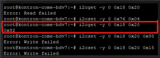
Voltage Read Commands: 

(8Bh) READ_VOUT---> 0C82H(value) 

(20h) VOUT_MODE--->82H(value)

Current Read Commands:

(8Ch) READ_IOUT--->0C42H.

Query:

1. Can we have some formula to convert the reeded value of Voltage and Current? Can give some examples to convert the reeded value into voltage & Current format.

2.  For Voltage check, what exponent value should be used for calculating voltage. even as per datasheet recommendation, exponent value need to write the getting the correct the voltage. but we are getting failure at           the time of writing.

3.For Current check, how to calculate current. it contains both the exponent and the mantissa. please give some examples for conversion of reeded value.

Thanks & regards,

Prasad Tatar


  • Hi Team,

    Waiting for reply.

  • Hi Tahar,

    Voltage Read Scenario:

    When we are trying with my target board, we are getting default value for VOUT_Mode is 82. and exponent we are getting out of range as per datasheet.

    as per datasheet, the range of exponent is -4 to -12 and when we decoded the 82 and exponent is -14. which is out of range. we try with 2 devices.

    and when we trying to change the Vout_Mode as per requirement VOUT_MODE must be 95 (Vout =0.8V). but we are getting failure when we try to write the VOUT_Mode.

    Our device required, this configuration ---> For voltages upto 1.5V, it is possible to support resolution upto 0.488mV/LSB (This requires VOUT_MODE = 0x95)

    and better give one-one example for start to end for Read and write to proper understanding.

    Thanks & regards,

    Prasad Tatar

  •  

    VOUT_MODE 82h (b'1000 0010) would decode to an Exponent value of 2, not -14.  With an exponent of 2 a VOUT_COMMAND value of 0C82 would be 12,808V, so I suspect something is not correct with your read of VOUT_MODE.

    Would it be possible to share what tools you are using to read VOUT_MODE so we might be able to understand why you are arriving at a value that is so far outside of the device's range?

    Based on your decode of VOUT_COMMAND, I suspect that your VOUT_MODE is actually 94h (b'1001 0100) which is an exponent -12 (b'10100 = -12).  For VOUT_MODE = 94h, VOUT_COMMAND 0C82h = 0.7817V 

    For changes to VOUT_MODE:

    VOUT_MODE is only writable when the output is disabled, so you will need to turn-off the output with the EN/UVLO pin or OPERATION command, as configured by the ON_OFF_CONFIG setting.

    I am attaching an excel file that can be used to encode / decode PMBus values into Linear11 and Linear16 to help.


    PMBUS_Value_Decoder.xlsx

    This article can provide some C-code to decode Linear 11 values, into floating point values

    https://embeddedartistry.com/blog/2018/07/05/linear11-conversion-using-a-sign-extension-bit-twiddling-hack/ 

  • Hi Peter,

    Thanks for the reply.

    We tried to write the Vout Mode value with EVAL Module. we are able to write the VOUT Mode value.

    We have now query regarding the VOut Mode Default Value.

    We are reading the Vout Mode value from Generic I2C(PMbus) and We are getting the default value is 82H.

    but when we are connecting to TI GUI and checking there, we are able to see the 97H default value. We checked the same scenario with our 2 devices.

    Kindly suggest here. 

    Regards,

    Prasad Tatar

  •  

    Can you provide a screen shot of the device from the FUSION GUI?

    The default address for the evaluation board is 0x24 (Address 36d) not address 0x18 as in your code above. 

    Could you be attempting to access the wrong device on the I2C bus?

  • Hi Peter,

    Please find the Inline response:

    Can you provide a screen shot of the device from the FUSION GUI?

    ---> FUSION GUI Readings taken from our device. Image attached below.

    The default address for the evaluation board is 0x24 (Address 36d) not address 0x18 as in your code above. 

    --->This Is not Evaluation board address this is our device address(0x18) 24d and last message attachment I2C Reading for our device only.

    By following. same process, we able to read the value of VOUT MODE is 97H. 

    Could you be attempting to access the wrong device on the I2C bus?

    --->We are reading all the slave devices, and we are getting the expected address.

  •  

    The FUSION GUI screen shot is showing Address 18h (24d) and the VOUT reading is consistent with VOUT_MODE = 0x97 (Relative Data Format, Exponent -9) which is the factory default value for VOUT_MODE for the TPS546A24A.

    I am not sure why I2CGet is returning 0x82 on the read of 0x20.  I even tried checking to see if this is the PEC byte on the read, but the PEC byte for a read from command code 0x20 on device 0x18 with data 0x97 should be 0xEA

    0x30 0x20 0x31 ox97 0xEA

    Do you have an oscilloscope or logic analyzer you can connect to CLK and DAT so we can look at what is being set over the bus when executing the i2cget command?