This thread has been locked.

If you have a related question, please click the "Ask a related question" button in the top right corner. The newly created question will be automatically linked to this question.

UCC2897A: Compensating the Feedback Loop gain in db

Part Number: UCC2897A

Hi Sir,

In the document "Understanding and Designing an Active Clamp Current Mode Controlled
Converter Using the UCC2897A" 

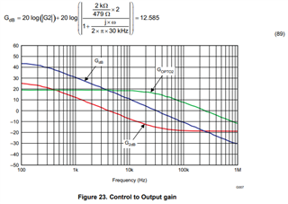
Can any one clarify below equation, how to get 12.5db at 8kHz frequency. 

I have considered all the parameters from the document. As per my matlab program, the answer is -6.3db at 8kHz. The code is given below for the reference. 

clc
s = tf('s');
Co = 660e-6;
Resr = 10e-3;
Vo =3.3;
Po = 100;
Rload_F = Vo^2/Po;
Rload_10 = Vo^2/(0.1*Po);
Ncs = 100;
N = 6; %22/12;
Rcs = 6.9; %0.347;
Io = Po/Vo;
Vref = 5;
Vfbmax = 2.4; %(0.95*1.27)*(5/2);
Irefmin = 1.3e-3;
Rvref = (Vref-Vfbmax)/Irefmin
% if CTR_min is 100 percentage
Ioptomin = Irefmin;
ITL431 = Ioptomin;
Vopto = 4.5;
Vf = 1.3;
Vsc = 1.24;
Fo = 8e3;
Ropto = ((Vopto-Vf-Vsc)/ITL431)/3
CTR = 2;
Gopto = (Rvref/479)*CTR;
GFs = ((s*Co*Resr*Rload_F)+Rload_F)/((s*(Rload_F+Resr)*Co)+1);
GF_mins = ((s*Co*Resr*Rload_10)+Rload_10)/((s*(Rload_10+Resr)*Co)+1);
K = (N*Ncs*Vo)/(Io*Rcs*(5));
G2db_atFo=20*log10(K)+20*log10((sqrt(((2*pi*Fo*Co*Resr*Rload_10)^2)+((Rload_10)^2))))+20*log10(1/(sqrt((2*pi*Fo*(Rload_10+Resr)*Co)^2+1)))
Goptodb_atFo = 20*log10(Gopto)+20*log10(1/sqrt(1+(2*pi*Fo*(1/(2*pi*30e3)))^2))
Gopen_db = G2db_atFo+Goptodb_atFo

Please clarify if my code have any mistakes. 

Thanks and Regards

Umamaheswararao

  • Hello again Umamaheswararao,

    I compared each of your equations to the application note.  I found two equations that don't exactly follow the application note (shown here).  Can you help me understand why these differ from the application note?

    GFs = ((s*Co*Resr*Rload_F)+Rload_F)/((s*(Rload_F+Resr)*Co)+1); Why is Rload in the numerator?  Should this be Eq 83?

    G2db_atFo=20*log10(K)+20*log10((sqrt(((2*pi*Fo*Co*Resr*Rload_10)^2)+((Rload_10)^2))))+20*log10(1/(sqrt((2*pi*Fo*(Rload_10+Resr)*Co)^2+1)))  Why is Rload in the numerator?  Should this be Eq 85?

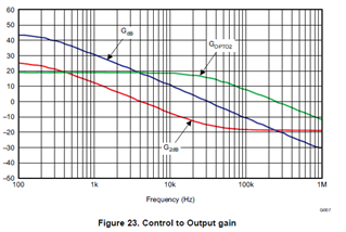
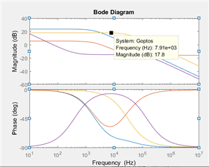
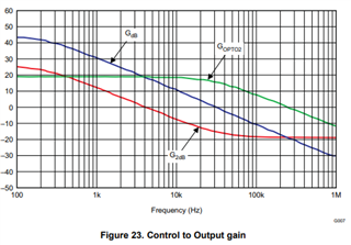
    Can you create a graph using your equations to sweep frequency and duplicate Figure 23 from the application note, see curves below?

    If you do this we can compare the two sets of curves to see where the difference(s) are.

    Regards,

    Eric

  • Hi Eric,

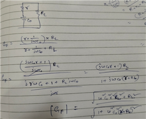
    Thank you for your time. From the derivation given below, I have added Rload term in the numerator. 

    In the application note, Rload term is missing in the numerator in Equation. 83, 85. 

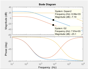
    Figure 23 is not matching If I plot same using the equations given in the application note. given below for your refrence


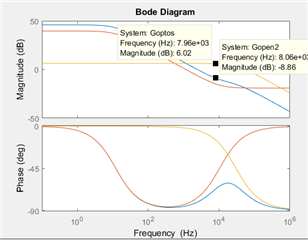
    Gopen2 ------ Gdb

    G2------- G2db

    Please suggest.

    As per the application note, the gain should be 12.585db, but from the Matlab plot it is coming -7.19db. 

    The revised code is given below

    clc
    s = tf('s');
    Co = 660e-6;
    Resr = 10e-3;
    Vo =3.3;
    Po = 100;
    Rload_F = Vo^2/Po;
    Rload_10 = Vo^2/(0.1*Po);
    Ncs = 100;
    N = 6; %22/12;
    Rcs = 6.9; %0.347;
    Io = Po/Vo;
    Vref = 5;
    Vfbmax = 2.4; %(0.95*1.27)*(5/2);
    Irefmin = 1.3e-3;
    Rvref = (Vref-Vfbmax)/Irefmin
    % if CTR_min is 100 percentage
    Ioptomin = Irefmin;
    ITL431 = Ioptomin;
    Vopto = 4.5;
    Vf = 1.3;
    Vsc = 1.24;
    Fo = 8e3;
    Ropto = ((Vopto-Vf-Vsc)/ITL431)/3;
    CTR = 2;
    Gopto = (Rvref/479)*CTR;
    GFs1 = ((s*Co*Resr)+1)/((s*(Rload_F+Resr)*Co)+1); % Eq.83 at full load from the application note
    GF_mins1 = ((s*Co*Resr)+1)/((s*(Rload_10+Resr)*Co)+1); % Eq.83 at 105 load from the application note
    % GFs = ((s*Co*Resr*Rload_F)+Rload_F)/((s*(Rload_F+Resr)*Co)+1);
    % GF_mins = ((s*Co*Resr*Rload_10)+Rload_10)/((s*(Rload_10+Resr)*Co)+1);
    K = (N*Ncs*Vo)/(Io*Rcs*(5)); % Eq. 80 from the application note
    % G2db_atFo=20*log10(K)+20*log10((sqrt(((2*pi*Fo*Co*Resr*Rload_10)^2)+((Rload_10)^2))))+20*log10(1/(sqrt((2*pi*Fo*(Rload_10+Resr)*Co)^2+1)))
    % Goptodb_atFo = 20*log10(Gopto)+20*log10(1/sqrt(1+(2*pi*Fo*(1/(2*pi*30e3)))^2))
    % Gopen_db = G2db_atFo+Goptodb_atFo
    G2db_atFo=20*log10(K)+20*log10((sqrt(((2*pi*Fo*Co*Resr)^2)+((1)^2))))+20*log10(1/(sqrt((2*pi*Fo*(Rload_10+Resr)*Co)^2+1)))
    Goptodb_atFo = 20*log10(Gopto)+20*log10(1/sqrt(1+(2*pi*Fo*(1/(2*pi*30e3)))^2))
    Gopen_db = G2db_atFo+Goptodb_atFo % Eq. 85 from the application note
    %bode(GF)
    %hold on
    %bode(GF_min)
    G1 = K*GFs1;
    G2 = K*GF_mins1;
    %G2db_atFo=20*log10(K)+20*log10((sqrt(((2*pi*Fo*Co*Resr*Rload_10)^2)+((Rload_10)^2))))+20*log10(1/(sqrt((2*pi*Fo*(Rload_10+Resr)*Co)^2+1)))
    Goptos = Gopto/(1+(s/(2*pi*30e3)));
    Gop = (Rvref/(1/((1/Ropto)+(1/(1e3+(1/(s*10e-6)))))))*(1/(1+(s/(2*pi*30e3))));
    %Goptodb_atFo = 20*log10(Gopto)+20*log10(1/sqrt(1+(2*pi*Fo*(1/(2*pi*30e3)))^2))
    %Gopen_db = G2db_atFo+Goptodb_atFo
    %total open loop uncompensated loop gain
    Gopen1 = Goptos*G1;
    Gopen2 = Goptos*G2;
    bode(Gopen2)
    hold on
    bode(G2)
    hold on
    bode(Goptos)

    Thanks and Regards

    Umamaheswararao

  • Hi Umamaheswararao,

    G2 is Gco at 10% load using Equation 85, Gopto is given by Equation 86 with 30 kHz in the denominator (3 kHz is a typo), and G_db is given by Equation 89.

    Regards,

    Eric

  • Hi Eric,

    Yes, I have considered 30kHz in the equation, you can see in the above post, 

    Goptos = Gopto/(1+(s/(2*pi*30e3)));

    Equation 89, is 

    G2db_atFo=20*log10(K)+20*log10((sqrt(((2*pi*Fo*Co*Resr)^2)+((1)^2))))+20*log10(1/(sqrt((2*pi*Fo*(Rload_10+Resr)*Co)^2+1)))
    Goptodb_atFo = 20*log10(Gopto)+20*log10(1/sqrt(1+(2*pi*Fo*(1/(2*pi*30e3)))^2))

    Gopen_db = G2db_atFo+Goptodb_atFo

    Waveform shape is same but not magnitude same is given below for your reference

    20logIG2I at 8kHz is -8.86db, 20logIG_optoI at 8kHz is 6 dB, sum of these two will result negative. but, as per application note it should be 12.29dB. Please check the code in my above post. 

    Regards

    Umamaheswararao

  • Well, at least we have the same shape now!  Maybe there is some typo in the Application note.  If you use G1 (full load) instead of G2 does it produce 12.29dB?

    Eric

  • I just noticed your Gopto gain is only 6dB.  In Figure 23 the low frequency Gopto is quite a bit higher, near 20dB.  Can you check that?

    Eric

  • Hi Eric,

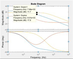
    Yes, may be this plot is at G1 (full load0, nearly same values are coming at Fco = 8kHz

    Gopto =

    8.0483


    G2db_atFo =

    -6.1898


    Goptodb_atFo =

    17.8157


    Gopen_db =

    11.6260

    Bode plot of the same is given below for your reference

    1. However, for the design of compensator what I have to consider, as per application note "G2" (10% load) is consider in equation 91 to calculate Rfb

    But, 12.5db is for G1 (full load).

    Please suggest.

    Thanks and Regards

    Umamaheswararao
  • Hi,

    I considered equation 86 to plot Goptos

    Gopto is same as appilcation note. 

  • Hi Umamaheswararao,

    Reply to first post about G1 - I was searching for a possible explanation. Later, I noticed the low frequency gain of the opto was different.  The best approach to set compensation is usually at light load, i.e. G2.  At light load RL is highest, the load pole moves to lowest frequency, and phase of the loop is minimum.  Do the compensation at light load.

    Reply to second post about Gopto(s) with pole at 3 kHz.  This is an unexpected result. Simply looking at the Gopto(s) formula with S=0 should produce the same gain whether the pole is at 3 kHz or 30 kHz.

    Can you manually force the value of Gopto (8.048 V/V) and produce/compare two graphs with the pole at 3 kHz and 30 kHz?

    Eric

  • Hi Eric,

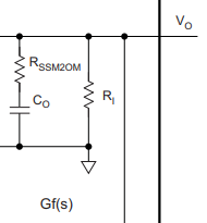
    Thank you for the reply. Yes, I can take the compensation at light load, but what about the Rload in the numerator as per below derivation. Is this correct expression for Gf (equation 84 from the application note)

    Please suggest. 

    Regards

    Umamaheswararao
  • Hi Umamaheswararao,

    According to the application note you don't need Rload in the numerator.

    Eric

  • Hi Eric, 

    I am not understanding this, as per the derivation, Rload is present in the numerator. Can you please explain. 

    Regards

    Umamaheswararao

  • Hi Umamaheswararao,

    If we look at the load, it's obvious the DC impedance (Vo/io) should be RL.  I suspect whoever wrote the Application Note normalized the transfer function for equation 83, but did not "un-normalize" it for equation 85 and the remainder of the paper.

    Equation 85 should have Rload in the numerator.  Maybe it's a typo.  Are the curves shown after equation 85 correct with, or without RL?

    I think your derivation for Gf(s) is correct and should be used.

    Eric

  • Hi,

    Equation (83) GF = Io/I1 involves parallel impedance of Rload and Cout, but GF itself is not an impedance, but a ratio, in general, although a transfer function can be an impedance.

    So to be clear, for development of a transfer function, it is helpful to write down what that transfer function is defined as, and what is intended to find.

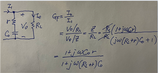
    Please look at the below for Equation (83) development. Rload on top and bottom are canceled out.

    If questions, please let's discuss.

    Please use Figure 18 on page 37 for each transfer function development. Also notice, Rload is moved into Equation (80), so Equation (80), (83 and (85) are all dimensionless.

    If you examine these three equations, you can find they are all dimensionless, or each is a ratio number without unit. Figure 21 and 22 are showing dimensionless as well.

    In other words, if Equation (83) x Rload, then its result should be with a unit ohm. But this is just for check purpose. The basis of Equation (80), (83) and (85) are all correct based on Figure 18 for each.

  • Hi,

    Thank you for the detailed explanation. Now, I understood the derivation of Gf.

    Regards

    Umamaheswararo