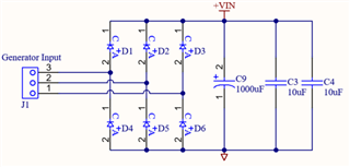
I built the circuit you see in the schematic
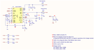
Input is 5.25V using the power supply, output voltage is 4.15 V and connected to another PCB I designed. Vbat is 4.05 V .
When I connect a Li-Ion battery to this circuit, I see that 2 mA current is drawn from the power supply. I can't see any current from ''jumper shorting'' when I try to measure Iout and Ibat.
I'm using SERTEC 3200mAh 3.7V 180409 Battery.
All LEDs are ON when I connect the battery. (LED1: Charge / LED2: Charge Done / LED3: Power Good)
The R6 and R8 you see in the schematic are not fitted.
What is wrong with this circuit? Why is the battery charging so slowly?
I can add if there is any information I forgot to mention.
Thanks.