This thread has been locked.

If you have a related question, please click the "Ask a related question" button in the top right corner. The newly created question will be automatically linked to this question.

TPS4811-Q1: IC goes broken on electronic load

Part Number: TPS4811-Q1

Hello TI, 

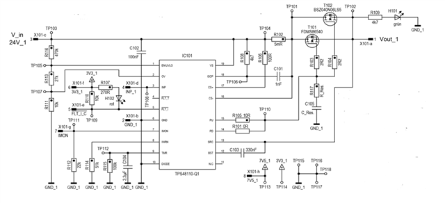
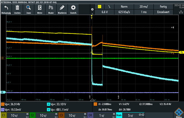
I have designed a circuit with the TPS48110. With this I would like to switch a MOSFET and monitor it. To test the overload protection I have connected the output to an electronic load. In doing so, it destroys on every test and has done so 6-8 times. It has only worked in one setup so far.
In addition, I also have your test board for the IC here. With this the testing with the setup works without problems.
Can you help me and say where the error is?

Thanks for your help

  • Hi Jan,

    Thanks for reaching out!

    Is it getting damaged during startup itself ?

    I didn't see any major issue in the schematic. What is the value of C105?

    Have you tried powering up with just resistive load instead of electronic load ?

    Can you increase C103 to 1uF and test again.

    Best Regards,

    Rakesh

  • Switching without load works without problems. When I connect the load to it, the MOSFET turns off and the IC is broken.
    With resistive load of about 1A it worked. Afterwards I tested a short circuit, which broke the IC again.

  • The capacitor C105 is not installed. Only intended as a placeholder

  • Looks like you are exceeding the abs max voltage spec either on Vs or SRC pins during turn off.

    Please add large cap or TVS diode at the input and schottky Diode at the output. You can get part numbers for the same from EVM schematic

    Please test and let me know if it helps

    Best regards 

    Rakesh

  • Hello Rakesh, 

    i have added to the circuit a TVS diode and a capacitance at the input, a shottky diode at the output and a resistor between supply voltage and VS pin as it is done in the demoboard. Then the circuit worked for both overload and short circuit also with electrical load.

    Then I removed components one by one again. The shottky diode and the input capacitance had no effect. Only when the resistor was removed did the error occur again and the IC broke.


    Do you have any idea why just this low pass at VS can make the difference?

    Best regards 

    Jan 

  • Hi Jan,

    Did you remove TVS diode at the input as well during testing the second time?

    The RC network at VS pin helps to filter short transient voltages reaching VS and does protect the controller

    Best regards 

    Rakesh

  • Hi Rakesh, 

    the TVS diode at the input was still installed when the IC broke again 

    Best regards

    Jan 

  • Hi Jan,

    Can you check the VS to GND pin voltage of the device during the condition to understand the level of transient voltage. 

    Best regards 

    Rakesh

  • Hi, Rakesh

    That's what I did. The following oscillogram was created (orange signal). The blue signal is the voltage on the Gate.

    Best regards

    Jan

  • Hi Jan,

    Let us have a call on the coming Tuesday to discuss. 

    I will send you my details in private 

    Best regards 

    Rakesh